Steel Bellows Clamping Shaft Coupling Stepped For Encoder
Product introduction
Bellows coupling uses corrugated thin-walled pipe (bellows) to directly weld or bond with the two half couplings to transmit motion. The coupling has the advantages of simple structure, small overall dimension, convenient processing and installation and high transmission accuracy. It is mainly used in small power precision machinery and control mechanisms requiring compact structure and high transmission accuracy.
1. The bellows coupling has no clearance and high sensitivity
2. High elasticity, better protection of equipment
3. It can absorb vibration and compensate radial, angular and axial deviations at the same time
4. Oil stain resistance and strong corrosion resistance
5. Torsional rigidity, clockwise and counterclockwise rotation characteristics are exactly the same
6. Commonly used in CNC machine tools, indexing discs and other industrial machinery
Products Features
>The material is aluminum alloy, and the middle bellows is made of stainless steel with excellent corrosion resistance
>Laser welding is used between bellows and shaft sleeve, with zero rotation clearance, suitable for forward and reverse rotation
>Bellows structure can effectively compensate radial, angular and axial deviation
>Designed for servo motor stepper motor
>Fastening method of clamping screw
Products Parameters
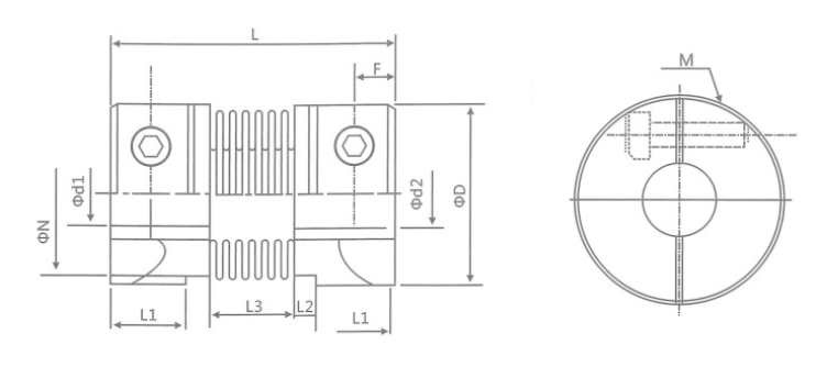
Product Drawings
Product Dimensions
model parameter | common bore diameter d1,d2 | ΦD | L | L1 | L2 | L3 | N | F | M | tightening screw torque (N.M) |
GRC-16x27 | 4,5,6,6.35,7,8 | 16 | 27 | 7.5 | 2 | 8 | 13.5 | 3 | M2.5 | 1 |
GRC-20x32 | 5,6,6.35,7,8,9,9.525,10 | 20 | 32 | 7.2 | 2.8 | 12 | 18 | 3.5 | M3 | 1.5 |
GRC-22.5x34 | 5,6,6.35,7,8,9,9.525,10,11,12 | 22.5 | 34 | 8.05 | 2.8 | 12.3 | 20.2 | 4.5 | M3 | 1.5 |
GRC-25x37 | 6,6.35,7,8,9,9,9.525,10,12 | 25 | 37 | 9.5 | 3 | 12 | 20.2 | 4.5 | M3 | 1.5 |
GRC-32x42 | 8,9,9.525,10,11,12,12.7,14,15 | 32 | 42 | 8 | 4 | 18 | 27.2 | 5.5 | M4 | 2.5 |
GRC-40x55 | 8,9,9.525,10,11,12,12.7,14,15,16,17,18,19,20 | 40 | 55 | 11.5 | 6 | 20 | 34.5 | 6.5 | M5 | 7 |
GRC-55x72 | 10,11,12,12.7,14,15,16,17,18,19,20,22,24,25 | 55 | 72 | 16.5 | 6 | 27 | 51.9 | 10 | M6 | 12 |
GRC-65x81 | 10,11,12,12.7,14,15,16,17,18,19,20,22,24,25,28,30,32,35,38 | 65 | 81 | 19.5 | 7 | 28 | 60.5 | 10.5 | M6 | 12 |
model parameter | Rated torque (N.M)* | allowable eccentricity (mm)* | allowable deflection angle (°)* | allowable axial deviation (mm)* | maximum speed rpm | static torsional stiffness (N.M/rad) | moment of inertia (Kg.M2) | Material of shaft sleeve | surface treatment | weight (g) |
GRC-16x27 | 0.8 | 0.1 | 1.5 | + 0.4 -1.2 | 9400 | 150 | 8.0x10⁻⁷ | High strength aluminum alloy | Anodizing treatment | 8 |
GRC-20x32 | 1.5 | 0.15 | 2 | + 0.6 -1.8 | 7600 | 220 | 2.2x10⁻⁶ | 13 | ||
GRC-22.5x34 | 1.8 | 0.15 | 2 | + 0.6 -1.8 | 6000 | 300 | 6.5x10⁻⁶ | 22 | ||
GRC-25x37 | 2.0 | 0.15 | 2 | + 0.8 -1.8 | 6100 | 330 | 6.9x10⁻⁶ | 30 | ||
GRC-32x42 | 2.5 | 0.2 | 2 | + 0.8 -2.5 | 4700 | 490 | 2.1x10⁻⁵ | 53 | ||
GRC-40x55 | 6.4 | 0.2 | 2 | + 0.8 -2.5 | 4200 | 530 | 2.3x10⁻⁵ | 97 | ||
GRC-55x72 | 12 | 0.2 | 2 | + 0.8 -2.5 | 3900 | 860 | 3.7x10⁻⁵ | 200 | ||
GRC-65x81 | 18 | 0.2 | 2 | + 0.7 -2.5 | 3500 | 900 | 3.6x10⁻⁵ | 380 |