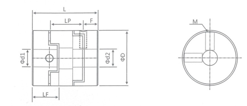
GH 20*25 M3 Oldham Type Shaft Coupling For Mechanism Connection
Products Introduction
Working principle of cross slider coupling: the two shafts are aligned by reaming holes and bolts, and the torque is transmitted by the compression and shear of the bolt rod; The shoulder on one coupling half is aligned with the groove on the other coupling half. The bolts connecting the two half couplings can be ordinary bolts of grade and B, and the torque is transmitted by the friction moment of the joint surface of the two half couplings. Generally, 45 steel is used. After surface heat treatment, its hardness is improved to a certain extent. However, some manufacturers use Q275 steel separately, so heat treatment is not required. The two couplings and the intermediate plate are combined. Although there is no relative rotation, the driving shaft runs at the same speed as the driven shaft to ensure the operation efficiency. The cross slider coupling is suitable for many occasions, such as tachometer, encoder, screw rod and industrial machinery.
Oldham type shaft coupling are designed to clamp evenly around the shaft and provide greater retention than fixed screw couplings without damaging shaft. Then tighten the clamping screws to secure. These are Oldham couplings
Products Parameters
Production Datasheet
model parameter | common bore diameter d1,d2 | ΦD | L | LF | LP | F | M | tightening screw torque (N.M) |
GH-16X18 | 4,5,6,6.35,7,8 | 16 | 18 | 7.1 | 11.6 | 3.55 | M3 | 0.7 |
GH-20X25 | 5,6,6.35,7,8,9,9.525 | 20 | 25 | 9.1 | 12.7 | 4.55 | M4 | 1.7 |
GH-25X28 | 5,6,6.35,8,9,9.525,10,11,12,14 | 25 | 28 | 11.7 | 16.65 | 5.58 | M4 | 1.7 |
GH-32x33 | 5,6,8,9,9.525,10,11,12,12.7,14,15,16 | 32 | 33 | 14 | 19.5 | 7 | M4 | 1.7 |
GH-40X35 | 8,9,9.525,10,11,12,12.7,14,14,16,17,18,19,20 | 40 | 35 | 15.5 | 18.4 | 7.75 | M4 | 1.7 |
GH-45X46 | 8,9,9.525,10,11,12.7,14,15,16,17,18,19,20,22 | 45 | 46 | 21.5 | 18.4 | 9 | M5 | 4 |
GH-50X38 | 10,12,12.7,14,15,16,17,18,19,20,22,24,25 | 50 | 38 | 16.5 | 15 | 8.25 | M5 | 4 |
GH-55X57 | 10,12,12.7,14,15,16,17,18,19,20,22,24,25,28,30,32 | 55 | 57 | 27 | 17.5 | 10.5 | M5 | 4 |
GH-63X47 | 14,15,16,17,18,19,20,22,24,25,28,30,32 | 63 | 47 | 21 | 17.5 | 10.5 | M6 | 8.4 |
GH-70X77 | 16,17,18,19,20,22,24,25,28,30,32,38,40 | 70 | 77 | 36.5 | 25 | 13.5 | M8 | 10.5 |
model parameter | Rated torque (N.M)* | allowable eccentricity (mm)* | allowable deflection angle (°)* | allowable axial deviation (mm)* | maximum speed rpm | static torsional stiffness (N.M/rad) | moment of inertia (Kg.M2) | Material of shaft sleeve | Material of shrapnel | surface treatment | weight (g) |
GH-16X18 | 0.7 | 0.8 | 3 | ±0.2 | 9000 | 30 | 3.3x10⁻⁷ | High strength aluminum alloy | P A 6 6 | Anodizing treatment | 6 |
GH-20X25 | 1.2 | 1.2 | 3 | ±0.2 | 7000 | 58 | 1.1x10⁻⁶ | 18 | |||
GH-25X28 | 2 | 1.6 | 3 | ±0.2 | 6000 | 130 | 3.1x10⁻⁶ | 25 | |||
GH-32x33 | 4.5 | 2 | 3 | ±0.2 | 4800 | 270 | 9.6x10⁻⁶ | 44 | |||
GH-40X35 | 9 | 2.4 | 3 | ±0.2 | 3600 | 520 | 2.3x10⁻⁵ | 81 | |||
GH-45X46 | 12 | 2.8 | 3 | ±0.2 | 3500 | 560 | 3.8x10⁻⁵ | 136 | |||
GH-50X38 | 19 | 2.6 | 3 | ±0.2 | 3000 | 800 | 1.8x10⁻⁴ | 142 | |||
GH-55X57 | 22 | 3.3 | 3 | ±0.2 | 2800 | 795 | 8.0x10⁻⁴ | 255 | |||
GH-63X47 | 19 | 3 | 3 | ±0.2 | 2500 | 1200 | 8.3x10⁻⁴ | 320 | |||
GH-70X77 | 56 | 3.8 | 3 | ±0.2 | 2500 | 1260 | 3.9x10⁻⁴ | 445 |