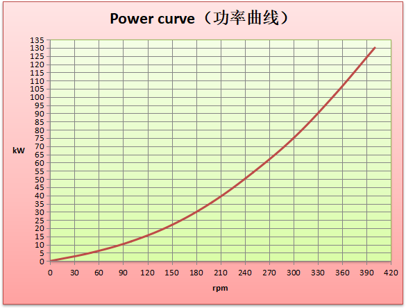
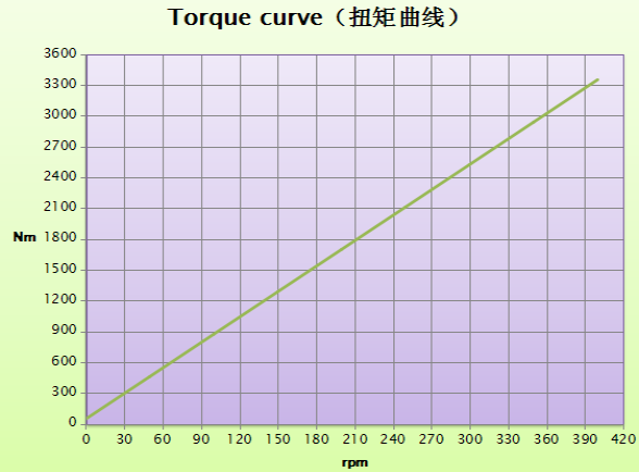
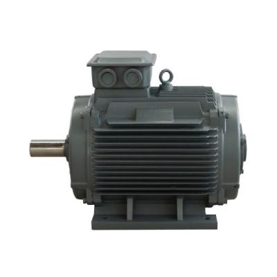
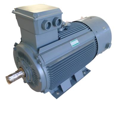
75kw 300rpm 400V 60HZ PMG PMSG Permanent Magnet Generator
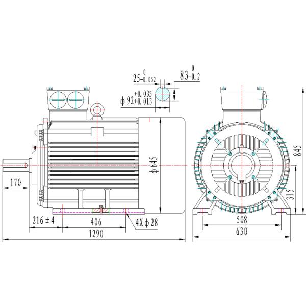
Product Drawing
Technical Parameter
No. | Parameter | Units | Data |
1 | Rated output power | KW | 75 |
2 | Rated speed | RPM | 300 |
3 | Rated output voltage | VAC | 440 |
4 | Rated current | A | 105 |
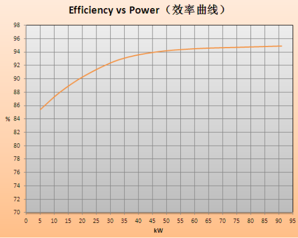
5 | Efficiency at rated speed | 94.6% | |
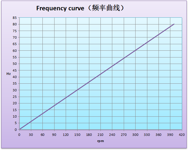
6 | Rated frequency | HZ | 60 |
7 | Poles | 24 | |
8 | Winding type | Y | |
9 | Insulation resistance | 20 MΩ | |
10 | Insulation | H class | |
11 | Rated torque | Nm | 2515 |
12 | Start torque | Nm | 46 |
13 | Temperature rise | °C | 90 |
14 | Bearing | SKF | |
15 | Weight | Kg | 960 |
16 | Design lifetime | Year | 20 |
Detailed Pictures
The permanent magnet generator is a device that converts mechanical energy to electrical energy. In this device, the rotor windings have been replaced with permanent magnets. Permanent magnet generators are used mostly in industrial applications like turbines and engines to produce commercial electrical energy, the permanent magnet alternator is an alternate source of energy and has multiple benefits which make it a great device for a variety of residential, commercial, and industrial applications.
The structure
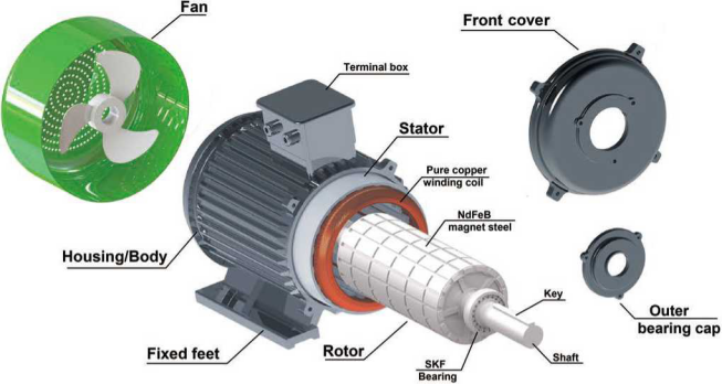
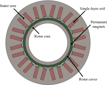
The permanent magnet generator is mainly composed of a rotor, end cover, and stator. The structure of the stator is very similar to that of an ordinary alternator. The biggest difference between the structure of the rotor and the alternator is that there are high-quality According to the position of the permanent magnet on the rotor, the permanent magnet generator is usually divided into a surface rotor structure and a built-in rotor structure.
Working Principle
- Magnetic Field Theory
The magnetic field theory is the fundamental principle behind the operation of a PMG. It states that a magnetic field is produced around a magnetic material, such as a permanent magnet, when it is subjected to an electric current. The strength of the magnetic field is directly proportional to the magnitude of the electric current flowing through the material.
The direction of the magnetic field is determined by the direction of the electric current. The magnetic field lines form a closed loop around the magnetic material, and the strength of the magnetic field decreases with distance from the material.
A PMG consists of a rotor, which is a rotating shaft, and a stator, which is a stationary component. The rotor is made up of a permanent magnet, which produces a magnetic field around it. The stator consists of a set of coils, which are wound around a magnetic core.
When the rotor rotates, the magnetic field produced by the permanent magnet interacts with the magnetic field produced by the coils in the stator. This interaction induces an electric current in the coils, which is then converted into electrical energy.
The strength of the electrical energy produced by the PMG is directly proportional to the strength of the magnetic field produced by the permanent magnet and the speed of rotation of the rotor. The faster the rotor rotates, the higher the frequency of the electrical energy produced.
In summary, the magnetic field theory is the fundamental principle behind the operation of a PMG. The interaction between the magnetic field produced by a permanent magnet and the magnetic field produced by a rotating shaft generates electrical energy, which can be used for various applications.
- Coil Design
The coil design of a permanent magnet generator is critical to its performance and efficiency. The design should take into account the number of turns, the wire gauge, and the shape and size of the coil.
The number of turns in the coil determines the voltage output of the generator. More turns will result in a higher voltage output, but also increase the resistance and decrease the current output. The wire gauge should be selected based on the current output required.
The shape and size of the coil should be designed to maximize the magnetic flux through the coil. This can be achieved by using a cylindrical or rectangular coil, depending on the shape of the magnet. The coil should also be positioned close to the magnet to maximize the magnetic field strength.
The coil should be made of high-quality copper wire with good insulation to minimize losses due to resistance and heat. The coil should also be designed to withstand the mechanical stresses of the rotating magnet and the centrifugal forces generated during operation.
Overall, the coil design of a permanent magnet generator plays a critical role in its efficiency and performance and should be carefully considered during the design process.
- Voltage and Current Production
A permanent magnet generator (PMG) produces both voltage and current through electromagnetic induction. The generator consists of a rotor with permanent magnets and a stator with wire coils. As the rotor spins, the magnets create a magnetic field that passes through the wire coils in the stator, inducing a voltage and current in the coils.
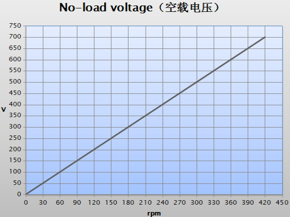
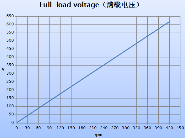
The amount of voltage and current produced by a PMG depends on several factors, including the strength of the magnets, the speed of the rotor, and the number of wire coils in the stator. The voltage produced is directly proportional to the speed of the rotor, while the current produced is proportional to the number of wire coils and the strength of the magnets.
PMGs are commonly used in wind turbines and hydroelectric systems to convert mechanical energy into electrical energy. They are also used in portable generators and other small-scale power generation systems.
Features
① The generator has many poles, which improve the frequency and efficiency, saving the cost of rectifiers and inverters.
② Finite Element Analysis is used when designing the generator, compact structure. Low startup torque, solves the problem of small wind startup, improving wind energy utilization.
③ Leave out the gear increaser, improve the reliability and efficiency of the generator, and lower the amount of maintenance.
④ H class insulation, vacuum pressure impregnation.
⑤ Have many structures such as vertical axis, horizontal axis, internal rotor, external rotor, and plate type.
⑥ Strong rotors, the generator could achieve high speed.
⑦ Small size, lightweight, high energy density, suitable for special situations.
⑧ Run efficiency throughout the whole speed range, high efficiency.
⑨ Use imported high-speed oil-contained bearings, maintenance free, and high reliability.
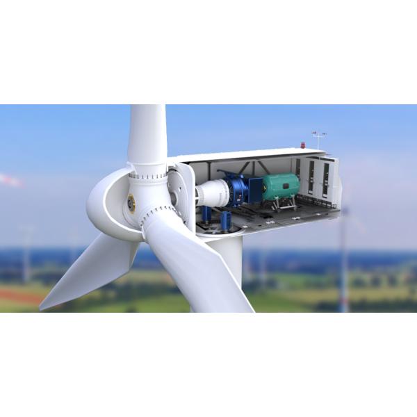
By matching the power and speed of the generator to that of the wind turbine, the power system becomes more efficient. No gearboxes are needed, and the efficiency of the alternator exceeds 90%.
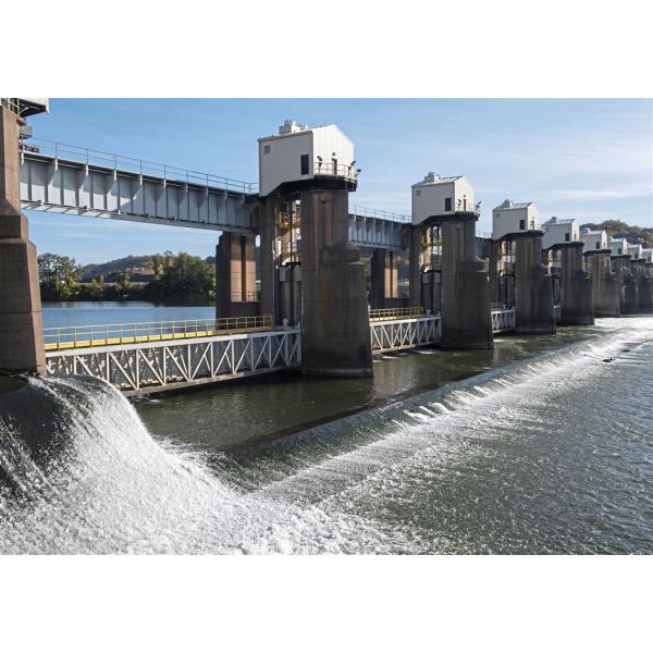
2. Variable speed generators provide a solution for Hydro Industry.
Increased efficiency from variable speed technology could make many more small hydro sites economically feasible to develop.
1. Free Energy Source
Permanent magnet generators produce electricity using their own magnetism. So, you do not need to pay high electric bills, and a large budget is saved. Besides, these devices do not need any other resources, which are quite environmentally friendly.
2. Reliable Power Output
Permanent magnet generators do not need any special operating environments. Hence, they can offer reliable performance compared with wind turbine motors. Additionally, permanent magnet generators do not suffer from energy loss, while induction generators typically lose 20-30% of energy. Additionally, there are no temperature rises in the magnetic machines, so the life of the bearings can be prolonged.
3. Low Maintenance Fee
Due to the features mentioned above, you do not need to spend lots of money and time on the maintenance of permanent magnet generators. And they do not have slip rings and brushes, which are supposed to be checked at regular intervals.
4. Compatibility
Permanent magnet generators can be employed with turbines and hydro turbines.