Order Codes:
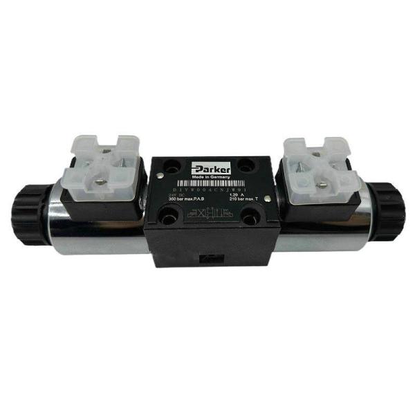
DG4V-3-2C-M-U-H7-60
DG4V-3-2A-M-U-H7-60
DG4V-3-8C-M-U-H7-60
DG4V-3-2AL-M-U-H7-60
DG4V-3-0B-M-U-H7-60
DG4V-3-6C-M-U-H7-60
DG4V-3-2N-M-U-H7-60
DG4V-3-0C-M-U-H7-60
DG4V-3-0A-M-U-H7-60
DG4V-3-7C-M-U-H7-60
General Description
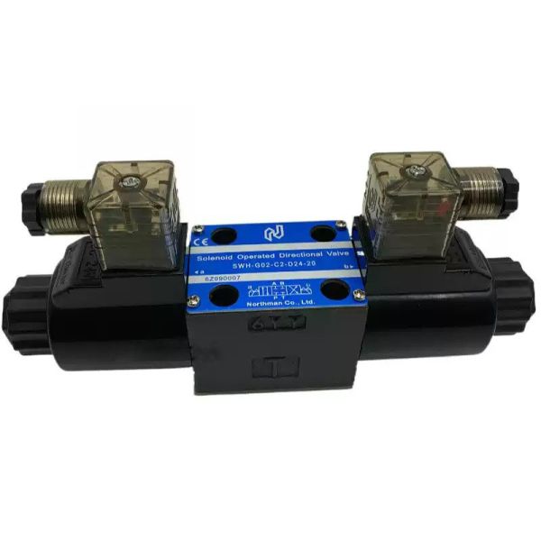
1. Solenoid operated directional control valves are for directing and stopping flow at any point in a hydraulic system.
2. Efficient control of greater hydraulic powers without increasing solenoid power consumption.
3. Installed cost and space savings from higher power/weight-and-size ratios.
4. Installation flexibility resulting from choice of numerous combinations of solenoid connectors and locations.
5. Viton seals as standard for multi-fluid capability. Nitrile seals available as a model code option.
6. Higher sustained machine productivity and higher uptime because of proven fatigue life and endurance,
tested over 20 million cycles.
7. Solenoid coils can be changed quickly and easily without leakage from hydraulic system.
8. Compact, cost effective system design when used with Eaton® SystemStak™ valves and subplates.
Operating Data | ||||||||
Feature DG4V-3 DG4V-3S DG4V-3R | ||||||||
Pressure Limits P, A and B ports 350 bar (5075 psi) 350 bar (5075 psi) 350 bar (5075 psi) | ||||||||
T port 210 bar (3045 psi) 100 bar (1450 psi) 210 bar (3045 psi) | ||||||||
Flow rating See performance data See performance data See performance data | ||||||||
Relative duty factor Continuous; ED = 100% Continuous; ED = 100% Continuous; ED = 100% | ||||||||
Type of protection: ISO 4400 coils with fitted correctly | IEC 144 class IP65 IEC 144 class IP65 IEC 144 class IP65 plug | |||||||
Coil winding Class H Class H Class H | ||||||||
Lead wires (coils type F***) Class H Class H Class H | ||||||||
Coil encapsulation Class F Class F Class F | ||||||||
Permissable voltage fluctuation: Maximum Refer to temperature limits. Refer to temperature limits. Refer to temperature limits. | ||||||||
Minimum 90% rated 90% rated 90% rated | ||||||||
Typical response times at 100% rated volts measured from application/removal of voltage to full spool displacement of “2C” spool at: | ||||||||
Flow rate P-A, B-T 40 l/min (10.6 USgpm) 20 l/min (5.3 USgpm) 20 l/min (5.3 Usgpm) | ||||||||
Pressure 175 bar (2537 psi) 175 bar (2537 psi) 175 bar (2527 PSI) | ||||||||
AC (~) energizing 15 ms 18 ms 18 ms | ||||||||
AC (~) de–energizing 23 ms 32 ms 32 ms | ||||||||
DC (=) energizing 45 ms 60 ms 60 ms | ||||||||
DC (=) de–energizing 28 ms 40 ms 40 ms | ||||||||
Power consumption, AC solenoids (for coils listed in model code). | Initial VA (RMS) ▲ | Holding VA (RMS) | Initial VA (RMS) ▲ | Holding VA (RMS) | Initial VA (RMS) | Holding VA (RMS) | ||
Full power coils: Dual frequency coils at 280 61 280 61 N/A 50 Hz | ||||||||
Dual frequency coils at 300 58 300 58 N/A 60 HZ | ||||||||
Low power coils, “BL” and “DL”: (Not available with “N” – No-spring detented models) | Low power coils not usable with DG4V-3S valves. | 170 37 N/A | ||||||
Dual frequency coils at – – 190 37 N/A 50 Hz | ||||||||
Dual frequency coils at – – – – N/A 60 Hz | ||||||||
Power consumption, Full power coils: 12V, model type “G” | DC solenoids at rated voltage and 20 30W – | C (68 F). 30W | – | N/A | ||||
24V, model type “H” | 30W – | 30W | – | N/A | ||||
Low power coils: 12V, model type “GL” | Low power coils not usable with DG4V-3S valves. | – | 18W | N/A | ||||
24V, model type “HL” | 18W | – | N/A | |||||
24V, HM Coil | 8W | – | N/A | |||||
n For applications where valves are to remain pressurized (either energized or de-energized) at pressures over 210 bar (3045 psi) without frequent switching, it is recommended to use the high performance model, DG4V-3. | ||||||||
▲ 1st half cycle; armature fully retracted. |
DG4V3-S/R- High Performance and Standard Performance Valves
1. Minimum pressure drop 2.5 bar at 30 l/min.
2. Range of coil connectors including DIN, Deutsch, AMP and terminal box.
3 Range of coil voltages and power options.
4. Up to 80 l/min (21 USgpm) and up to 40 l/min (10.5USgpm) respectively at 350 bar (5000 psi).
5. Offers designers the opportunity to select the optimum value package for each application.
6. International standard interface. The valve mounting face conforms to ISO 4401, size 03 and is compatible with related international standards.
Max Pressure: 350Bar
Relative : ED=100%
Protection Class: IP65
Coil Winding: Class H
Lead wire: Class H
Coil encapsulation : Class F
Working Pressure: 175bar
Power of Coil: 30W ,18W