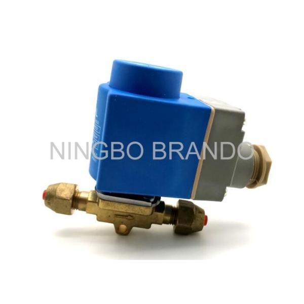
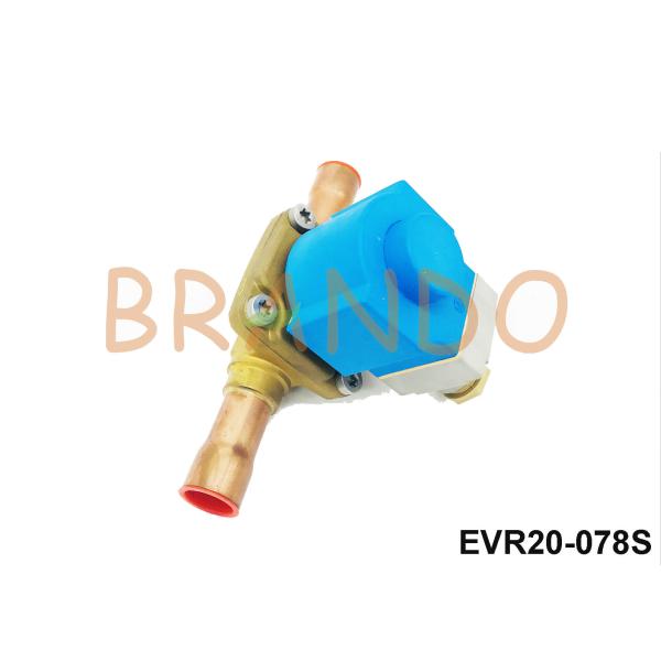
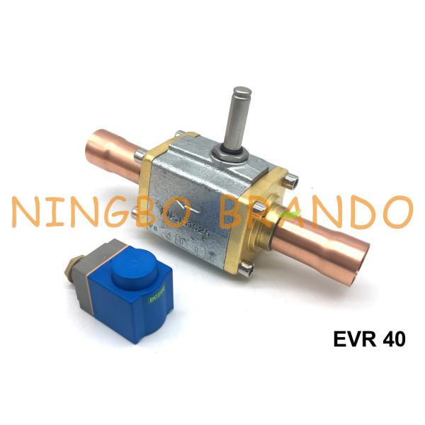
1068/3 Diaphragm Pilot Operated ODS 3/8'' Cooling Solenoid Valve
1068/3S: 3/8'' Inch Diaphragm Pilot Operated NC Refrigeration Solenoid Valve ODS Connection Without Coil.
1068/3A6: 3/8'' Inch Diaphragm Pilot Operated NC Refrigeration Solenoid Valve ODS Connection With 220/230 VAC(A6) Coil.
1068/3A7: 3/8'' Inch Diaphragm Pilot Operated NC Refrigeration Solenoid Valve ODS Connection With 240 VAC(A7) Coil.
HF2 HF3 HM2 HM3 HM4 CM2 Coil can be mounted on the valve.
Castel type solenoid valve is consist of Brass body, Stainless Steel plunger armature, coil and other parts.
The valve series 1034 ; 1038 ; 1040 ; 1048 ; 1049 ; 1050 ; 1058 ; 1059 ; 1078 (/11 , /13 , /M42) ; 1079 (/13 , /M42 , /17) ; 1098/9 ; 1099/11 are piston pilot-operated valves. Their operation depends not only on the magnetic field produced by the current flow into the coil, but also on a minimum inlet pressure, which is necessary to:
• open the piston and keep it lifted off the main opening
• close the piston and ensure the tightness on the main opening
Opening/closing of main valve seat is controlled by the piston, while opening/closing of pilot seat is controlled by the mobile plunger of the coil.
This operation depends not only on the magnetic field generated by the current flowing into the coil, but also minimal inlet pressure to move the diaphragm and keep it off the main valve seat. The opening / closing of the main valve seat is controlled by a diaphragm, while the opening / closing of the pilot valve seat is controlled by a movable plunger. These valves cannot be operated at zero differential pressure.
The solenoid valve is designed to shut off the flow when receiving an electrical signal. They are used in refrigeration systems with all common chlorofluorinated refrigerants.
Main characteristics:
1. Connection diameter 12 mm.
2. The diameter of the valve seat is 12.5 mm.
Features:
1. The valve is normally closed (NC), i.e. if the coil is de-energized, the piston blocks the flow of refrigerant.
2. Comes with an HM2 220/230 VAC electromagnetic coil.
3. The connector required for electrical connection (9150 / R01 or 9150 / R02) must be ordered separately.
4. Dimensions (length × width × height) and weight: (127mmx45mmx91mm)
Analogs from other manufacturers:
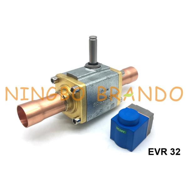
s type EVR10 (We also supply)
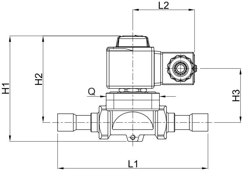
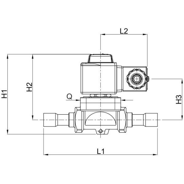
Dimension:
Model | Connection | Dimension | Coil Type | |||
SAE (Flare), ODF (Solder) | H1 | H2 | L1 | Q | HM2 HM3 | |
1020/2 | 1/4'' SAE | 75 | 62.5 | 58 | - | |
1020/3 | 3/8'' SAE | 65 | ||||
1028/2 | 1/4'' ODF | 32.5 | 125 | |||
1028/3 | 3/8'' ODF | 62.5 | 125 | |||
1064/3 | 3/8'' SAE | 82 | 69.5 | 68 | ||
1064/4 | 1/2'' SAE | 72 | ||||
1068/3 | 3/8'' ODF | 111 | ||||
1068/4 | 1/2'' ODF | 127 | ||||
1070/4 | 1/2'' ODF | 91 | 75.0 | 100 | 45 | |
1070/5 | 5/8'' ODF | 106 | ||||
1078/4 | 1/2'' ODF | 127 | ||||
1078/5 | 5/8'' ODF | 173 | ||||
1078/9 | 1 1/8'' ODF | 115 | 96.0 | 250 | 80 | |
1078/11 | 1 3/8'' ODF | 172 | 138.0 | 278 | 68 | |
1090/5 | 5/8'' SAE | 106 | 78.0 | 120 | 57 | |
1090/6 | 3/4'' SAE | 106 | 78.0 | 124 | 57 | |
1079/7 | 7/8'' ODF | 91 | 75.0 | 190 | 45 | |
1079/11 | 1 3/8'' ODF | 115 | 96.0 | 292 | 80 | |
1079/13 | 1 5/8'' ODF | 172 | 138.0 | 278 | 68 | |
1098/7 | 7/8'' ODF | 106 | 78.0 | 180 | 57 | |
1099/9 | 1 1/8'' ODF | 106 | 78.0 | 216 | 57 | |
1099/11 | 1 3/8'' ODF | 157 | 127.0 | 291 | 68 |
Technical Data:
Operating Principles | Model Number | SAE Port | Seat size nominal Ø (mm) | Kv Factor (m³/h) | PS (bar) | TS(℃) | TA(℃) | ||
min | max | min | max | ||||||
Direct Acting | 1020/2 | 1/4'' | 2, 5 | 0, 175 | 45 | -35 | +110 | -35 | +50 |
1020/3 | 3/8'' | 3 | 0, 23 | ||||||
Diaphragm Pilot Operated | 1064/3 | 3/8'' | 6, 5 | 0, 80 | 45 | -35 | +105 | -35 | +50 |
1064/4 | 1/2'' | ||||||||
1070/4 | 1/2'' | 12, 5 | 2, 20 | ||||||
1070/5 | 5/8'' | 2, 61 | |||||||
1090/5 | 5/8'' | 16, 5 | 3, 80 | ||||||
1090/6 | 3/4'' | 4, 80 | |||||||
Piston Pilot Operated | 1034/3 | 3/8'' | 6, 5 | 1, 00 | 45 | -35 | +110 | -35 | +50 |
1034/4 | 1/2'' | ||||||||
1040/4 | 1/2'' | 12, 5 | 2, 40 | ||||||
1040/5 | 5/8'' | 3, 00 | |||||||
1050/5 | 5/8'' | 16, 5 | 3, 80 | ||||||
1050/6 | 3/4'' | 4, 80 |
What are the important parts of a chiller refrigeration system and common faults?
The main components of the chiller refrigeration system are compressor, condenser, evaporator, expansion valve (or capillary, subcooling control valve), four-way valve, double valve, check valve, solenoid valve, pressure switch, melting plug, output pressure Regulating valves, pressure controllers, reservoirs, heat exchangers, collectors, filters, dryers, automatic shutters, shut-off valves, liquid plugs, and other components.
It is necessary to know more about the possible failures of various components of the chiller and to eliminate and repair them in time. The following describes the common faults of solenoid valves on chillers:
1. The solenoid valve cannot be opened and operated normally, or the power supply voltage is too low; or the circuit is in poor contact, that is, the circuit breaker or the coil is short-circuited, and can be inspected by a multimeter;
2. The valve of the solenoid valve is not closed tightly, or the installation direction of the solenoid valve is reversed, that is, the direction of fluid flow is opposite to the flow direction required by the solenoid valve, and the flow direction arrow on the valve body can be checked to confirm;
3. If the solenoid valve chip has dirt, the chip is stuck, causing the closure to be not tight or unable to close;
4. If the pressure difference between the inlet and outlet of the solenoid valve is greater than the valve opening capacity, the solenoid valve will not open;
Installation:
Before connecting the valve to the pipe, it is advisable to make sure that the refrigerating system is clean. In fact, valves with P.T.F.E. gaskets, and particularly piston valves, are sensitive to dirt and debris. Furthermore, check that the flow direction in the pipe corresponds to the arrow stamped on the valve body. All the valves can be mounted in any position so long as the coil does not point downwards. The brazing of valves with solder connections should be carried out with care, using a low melting point filler material. It is not necessary to disassemble the valves before brazing, but it is important to avoid direct contact between the torch flame and the valve body, which could be damaged and compromise the proper functioning of
the valve.
Before connecting a valve to the electrical system, be sure that the line voltage and frequency correspond to the values marked on the coil.
Focus on your demands, Offer you best solution:
√ Contact us if some points you have doubt
√ Contact us if somewhere need to change
√ Contact us if not the one you are looking for
√ Contact us if you are doing designing
Welcome to your any question and inquiry!