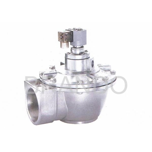
G2 1/2" Inches Straight-through Pneumatic Pulse Valve AC 220v Aluminium Solenoid Valve DMF-T-62S
The angle between the inlets of the straight-through electromagnetic pulse valve is 180°, the inlet is linked to the air reservoir, and the outlet is linked to the blow pipe. The air flow is smooth, and it can provide the pulse of cleaning gas that meets the requirements..
Our company specializes in the production of electromagnetic pulse valves. The inlet and outlet ports of DMF-T-62S are 2.5 inches in diameter and are suitable for large-scale cleaning equipment.
Please contact us if necessary!
Ordering Code:
Ordering code | Port Size | Orifice | Flow Value | |
G Threaded | mm | Kv | Cv | |
DMF-T-20 | 3/4” | 3.5-6 | 15.78 | 18.42 |
DMF-T-25S | 1” | 8-10 | 18.55 | 21.65 |
DMF-T-40S | 1 1/2” | 12-16 | 45.62 | 53.24 |
DMF-T-50S | 2” | 18-28 | 50.77 | 59.25 |
DMF-T-62S | 2 1/2” | 27-38 | 111.67 | 130.32 |
Basic situation of pluse valve DMF-T-62S:
Ref.number | Kv/Cv | Blwing Area | inlet and Out Pipe Size | Weight | Packing Dimension |
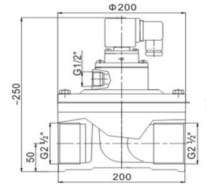
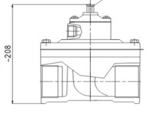
DMF-T-62S | 111.67/130.32 | 27-38 | G2 1/2" G2 1/2" | 3.95 | 20X20X24.3 |
Dimensions:
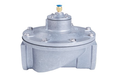
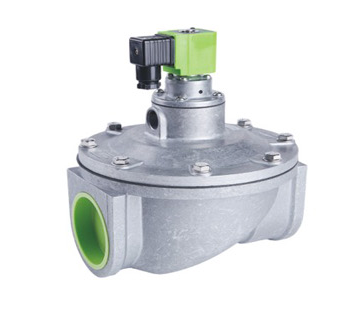
More pictures:
working principle:
The electromagnetic pulse valve is composed of an electromagnetic pilot head, a diaphragm and a valve body. The area of the diaphragm rear cavity is larger than the area of the front cavity, and the air pressure force is large, so that the diaphragm is in the closed position.
The electric controller inputs the electric signal, so that the electromagnetic pilot head sucks the moving column, opens the unloading hole, and
the pressure gas in the diaphragm back cavity is quickly discharged, the pressure gas in the front cavity of the diaphragm lifts the diaphragm, opens the channel, and the pulse valve performs Spray
The electric pulse signal disappears, and the spring of the electromagnetic pilot head immediately resets the movable column to close the unloading hole. The gas pressure and the spring force of the diaphragm rear cavity close the diaphragm passage, and the solenoid valve stops blowing.
Installation:
1. Prepare supply and blowtube pipes to suit valve specification. Avoid installing valves underneath the tank.
2. Ensure tank and pipes are free from dirt, rust or other particulate.
3. Ensure supply air is clean and dry.
4, Mount valves to inlet pipes and blowtube to valves, ensuring no excess thread sealant can enter the valve itself.
5. Make electrical connections to solenoid or connect RCA pilot port to pilot valve (RCA valves only).
6. Apply moderate pressure to system and check for installation leaks.
Our company can give you the best quality service and products, we hope you can choose us!