GENERAL DESCRIPTION
MX26631DL is a 40V industrial eFuse solution. The device provides robust protection for all systems and applications powered from 4.5V to 40V. For hot-pluggable boards, the device provides hot-swap power management with in-rush current control and programmable output voltage slew rate
features using the dVdT pin. Load, source, and device protections are provided with many programmable features including overcurrent,overvoltage and undervoltage. The precision overcurrent limit helps to minimize over design of the input power supply, while the fast responseshort circuit protection immediately isolates the faulty load from the input supply when a short circuit is detected.The device features fast reverse current blocking response. The internal robust protection control blocks of the MX26631DL along with its 40V rating, helps to simplify the system designs for the industrial surge compliance ensuring complete protection of the load and the device.
APPLICATIONS
Industrial Applications
Servers
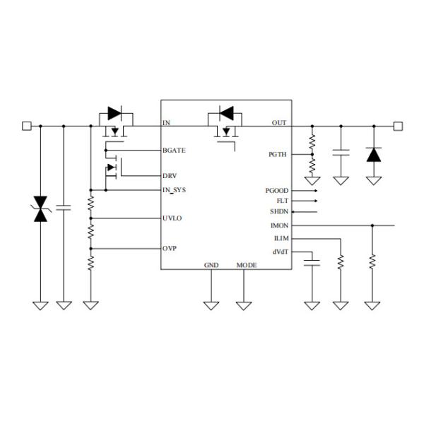
Minimum system application
Networking
Electronics breakers
FEATURES
♦ 4.5V to 40V operating input range
♦ Internal 60V, 30mΩ Ron hot-swap N-Channel FET
♦ Reverse blocking current in 0.2us
♦ Integrated current sensing with sense output
♦ Adjustable current limit from 0.6A to 6A
♦ Adjustable UVLO, OVP cutoff, output slew rate control for inrush current limiting
♦ Power Good Output (PGOOD)
♦ Overcurrent fault response with auto-retry
♦ Models with 1.5x pulsed overcurrent support
Absolute maximum ratings
Parameter | Value |
IN, IN_SYS, OUT, UVLO, FLT, PGOOD, PGTH | -0.3~60V |
IN, IN_SYS (10ms transient) | -0.3~65V |
BGATE | -0.3~65V |
DRV | -0.3~65V |
DRV - IN_SYS | -0.3~15V |
OVP, dVdT, IMON, MODE, SHDN, ILIM | -0.3~5.5V |
Junction temperature TJ | -40 to 150℃ |
Ambient temperature TA | -40 to 85℃ |
Storage temperature TSTG | -55 to 150℃ |
ESD(HBM) | ±2.0kV |
Leading temperature (soldering, 10secs) | 260℃ |
Note: stresses beyond those listed under “absolute maximum ratings” may cause permanent damage to the device. These are stress ratings only, functional operation of the device at theseor any other conditions beyond those indicated under “recommended operating conditions” is not implied. Exposure to absolute maximum rated conditions for extended periods may affect device reliability.
Recommended operating condition
Symbol | Parameter | Range |
IN_SYS, IN | Input Voltage | 4.5~40V |
OUT, UVLO, PGTH, PGOOD, FLT | 0-40V | |
OVP, dVdT, IMON, MODE, SHDN | 0~5V | |
ILIM | Resistance | 5~ 100kΩ |
IMON | ≥1kΩ | |
IN, IN_SYS, OUT | Capacitance | ≥100nF |
dVdT |
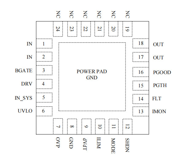
Terminal assignments
PIN NO. | PIN name | Description |
1/2 | IN | Power input. Connect to the Drain of the internal FET. |
3 | BGATE | Blocking FET gate driver output. Connect to GATE of the external FET. If external FET is not used, then leave BGATE pin floating. |
4 | DRV | Blocking FET fast pull-down switch drive. Connect DRV to the GATE of external pull-down switch. Leave this pin floating if external FET is not used |
5 | IN_SYS | Power input and supply voltage of the device. Short IN_SYSto IN in case blocking FET is not used. |
6 | UVLO | Input for setting the programmable UVLO threshold. Connect UVLO pin to GND to select the internal default threshold. |
7 | OVP | Input for setting the programmable OVP threshold. Connect to GND if OVP not used. |
8 | GND | System ground pin. |
9 | dVdT | A capacitor from this pinto GND sets output voltage slew rate. |
10 | ILIM | A resistor from this pinto GND sets overload and short circuit current limit. |
11 | MODE | Mode selection for ILIM pin short protection mode. This pin is pulled up internal. |
12 | SHDN | Pulling SHDN pin low makes the device to enter shutdown mode. Cycling SHDN pin voltage resets the device that fast latched off due to a fault condition. |
13 | IMON | Analog current monitor. A resistor from this pinto GND converts current to voltage. If unused, leave it floating. |
14 | FLT | Fault event indicator. It is an open drain output. If unused, leave floating or connect to GND. |
15 | PGTH | PGOOD comparator input. |
16 | PGOOD | Active high. A high indicates PGTH has crossed the VPGTHR threshold, and the internal driver is high. PGOOD goes low when VPGTH hits VPGTHF threshold. If PGOOD is unused connect to GND or leave it floating. |
17/18 | OUT | Power output of the device. |
19~24 | NC | No connect. |
Power Pad | Ground. |