The MX25947 family of electronic fuses are highly integrated circuit protection and power management solutions in small packages. The device uses very few external components and offers multiple protection modes. They are effective against overloads, short circuits, voltage surges, excessive inrush currents and reverse currents. The current limit level can be programmed with an external resistor. An internal circuit will off the internal FET to protect overvoltage. Applications with special voltage ramp requirements can use a single capacitor to program dVdT to ensure the proper output ramp rate.
FEATURES
♦Operating input voltage range VIN: 4.5V~24V
♦Integrated 28mΩ-on MOS Field Effect Transistor ♦ 1.34V Reference for Overvoltage protection
♦ 1A to 5A Adjustable Current ILIMIT
♦Programmable OUT slew rate, undervoltage lockout (UVLO)
♦Built-in thermal shutdown
♦ 10 Pin DFN3*3 & ESOP8L
APPLICATIONS
• Adapter powered devices
• Hard Disk Drives (HDD) and Solid State Drives (SSD)
• Set-top box
• Server/auxiliary (AUX) power
• Fan control
• PCI/PCIe cards
Ordering information
Part Number | Description |
MX25947D33 | DFN3*3-10L |
MX25947ES | ESOP-8L |
MPQ | 3000pcs |
Package dissipation rating
Package | RθJA (℃/W) |
DFN3*3-10L | 50 |
ESOP-8L | 60 |
Absolute Maximum ratings
Parameter | Value |
VIN | -0.3 to 30V |
VIN (10 ms Transient) | 33V(max) |
OUT | -0.3 to VIN+0.3 |
IOUT | 5A |
ILIM ,EN/UVLO ,dVdT | -0.3V to 7V |
BFET | -0.3V to 40V |
Junction temperature | 150℃ |
Storage temperature, Tstg | -55 to 150℃ |
Leading temperature (soldering, 10secs) | 260℃ |
ESD Susceptibility HBM | ±2000V |
Stresses beyond those listed in Absolute Maximum Ratings may cause permanent damage to the device. Exposure to absolute maximum rating conditions for extended periods may affect reliability. Functional operation of the device at any conditions beyond those indicated in the Recommended Operating Conditions section is not implied.
Recommended operating condition
Symbol | Range |
VIN | 4.5V to 24V |
dVdT ,EN/UVLO ,OVP | 0V to 6V |
ILIM | 0V to 3V |
IOUT | 0A to 4A |
Ambient temperature | -40~85℃ |
Operating temperature | -40~125℃ |
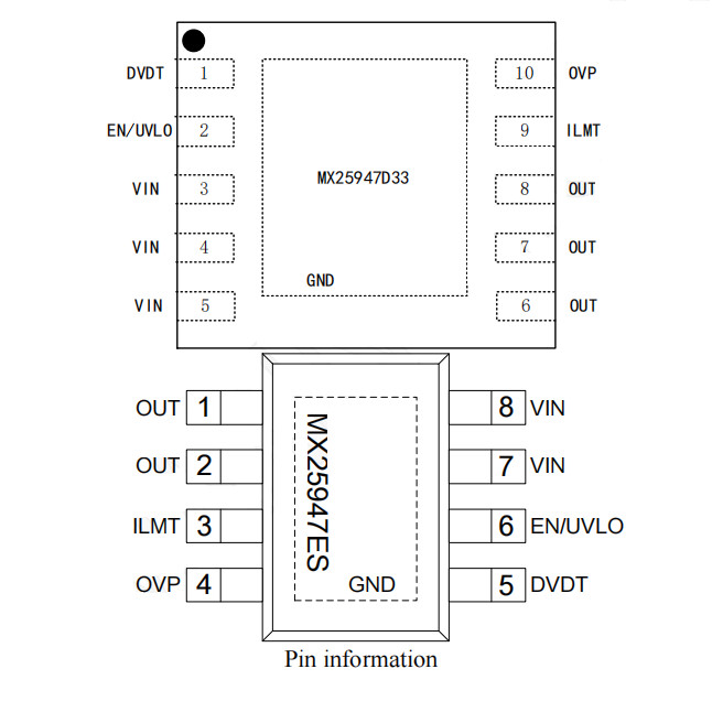
TERMINAL ASSIGMENTS
PIN NO. | PIN name | Description | |
DFN3*3 | ESOP8 | ||
1 | 5 | dVdT | Tie a capacitor from this pinto GND to control the ramp rate of OUT at device turn-on. |
2 |
6 |
EN/UVLO | This is a dual function control pin. When used as an ENABLE pin and pulled down, it shuts off the internal pass MOSFET. As an UVLOpin, it can be used to program different UVLOtrip point via external resistor divider. |
3~5 | 7 ,8 | VIN | Input supply voltage |
6~8 | 1 ,2 | OUT | Output of the device |
9 | 3 | ILIM | A resistor from this pinto GND will set the overload and short circuit limit. |
10 | 4 | OVP | External over voltage protection via resistor divider. The reference voltage is 1.34V (typical). |
Thermal Pad | GND | Ground |
Electrical characteristics
( VIN=12V, VEN/UVLO=2V, RILIM = 100kΩ, CdVdT = OPEN. TA=25℃, unless otherwise noted)
Symbol | Parameter | Test condition | Min | Typ. | Max | Unit |
VIN PIN | ||||||
VUVO | UVLO threshold, rising | 4.0 | 4.2 | 4.5 | V | |
UVLO threshold, falling | 3.8 | 4.0 | 4.3 | V | ||
IQON | Supply current | Enabled: EN/UVLO = 2V | 0.5 | 0.6 | 0.7 | mA |
IQOFF | EN/UVLO = 0V | 0.10 | 0.18 | 0.25 | ||
EN/UVLO | ||||||
VENR | EN Threshold voltage, rising | 1.30 | 1.34 | 1.38 | V | |
VENF | EN Threshold voltage, falling | 1.25 | 1.30 | 1.35 | V | |
IEN | EN Input leakage current | 0V ≤ VEN ≤ 5V | -100 | 0 | 100 | nA |
dVdT | ||||||
IdVdT | dVdT Charging current | 0.2 | μA | |||
RdVdT_disch | dVdT Discharging resistance | 60 | 80 | 100 | Ω | |
VdVdTmax | dVdT max capacitor voltage | 5.5 | V | |||
GAINdVdT | dVdT to OUT gain | 4.85 | V/V | |||
ILIM | ||||||
IILIM | ILIM Bias current | 0.5 | μA | |||
IOL |
Overload current limit | RILIM = 4.3kΩ, VVIN-OUT = 1V | 4.6 | 5 | 5.6 | A |
RILIM = 10kΩ, VVIN-OUT = 1V | 2.5 | 3.0 | 3.5 | A | ||
RILIM = 51kΩ, VVIN-OUT = 1V | 1.0 | 1.5 | 2.0 | A | ||
RILIM = 100kΩ, VVIN-OUT = 1V | 0.8 | 1.0 | 1.5 | A | ||
IOL R Short | Overload current limit | RILIM = 0Ω, Shorted Resistor Current Limit | 1.8 | A |
Symbol | Parameter | Test condition | Min | Typ. | Max | Unit |
IOL-R-Open | Overload current limit | RILIM = OPEN, Open Resistor Current Limit | 1.6 | A | ||
ISCL |
Short-circuit current limit | RILIM = 5kΩ, VVIN-OUT = 12V | 4.0 | 4.25 | 4.5 |
A |
RILIM = 10kΩ, VVIN-OUT = 12V | 2.76 | 2.88 | 3.0 | |||
RILIM = 51kΩ, VVIN-OUT = 12V | 1.06 | 1.14 | 1.22 | |||
RILIM = 100kΩ, VVIN-OUT = 12V | 0.86 | 0.94 | 1.0 | |||
RATIOFASTRIP | Fast-Trip comparator level w.r.t. overload current limit | IFASTRIP : IOL | 160 | % | ||
VOpenILIM | ILIM Open resistor detect threshold | VILIM Rising, RILIM = OPEN | 3.2 | V | ||
RDS (on) | FET ON resistance | 21 | 28 | 37 | mΩ | |
IOUT-OFF-LKG | OUT Bias current in off state | VEN/UVLO = 0V, VOUT = 0V (Sourcing) | 3 | μA | ||
IOUT-OFF-SINK | VEN/UVLO = 0V, VOUT = 300mV (Sinking) | 10 | μA | |||
OVP | ||||||
VREF_OVP | External ovp threshold | OVP rising | 1.30 | 1.34 | 1.38 | V |
VOVPF | OVP hysteresis | 1.25 | 1.30 | 1.35 | V | |
TSD | ||||||
TSHDN | TSD Threshold, rising | 131 | ℃ | |||
TSHDNhyst | TSD Hysteresis | -15 | ℃ | |||
Timing Requirements | ||||||
TON | Turn-on delay | EN/UVLO → H to IIN = 100mA, 1A resistive load at OUT | 900 | μs | ||
tOFFdly | Turn Off delay | 20 | μs | |||
dVdT | ||||||
tdVdT |
Output ramp time | EN/UVLO → H to OUT = 11.7V, CdVdT = 0 | 1 | ms | ||
EN/UVLO → H to OUT = 11.7V, CdVdT = 1nF | 10 | ms | ||||
ILIM | ||||||
tFastOffDly | Fast-Trip comparator delay | IOUT > IFASTRIP to IOUT= 0 (Switch Off) | 350 | ns |