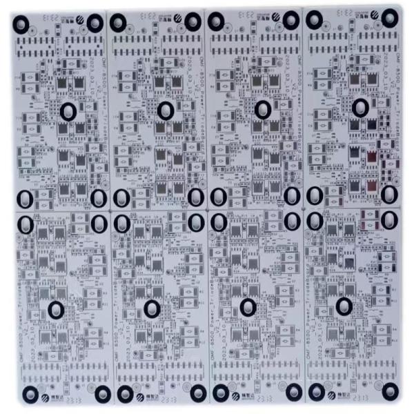
Printed Circuit Boards 4 Layer PCB Green Solder Mask
PCB Requirements:
1 The following marks should be printed from the component side: UL Logo, Material Code, Flammability Rating, Manufacturer name or symbol as indicated in UL yellow card. This should be printed with ink.
2 PCB thickness and drill hole size specified are finished sizes.
3 The tool mark for pcb if used should be a blind hole i.e no copper or mask should be present around the tool mark from either side of the pcb.
4 All holes should be concentric with the pad center by 0.02 minimum.
5 Add date code with ink on top side, preferred format YYWW(YEAR WEEK)
6 Lead free pcbs should be marked with rohs log as shown.
7 The vendor to provide material certification for ROHS compliance with every lot and packing to be identified with PB free symbol.
S1130 Data Sheet:
S1130 | |||||
Items | Method | Condition | Unit | Typical Value | |
Tg | IPC-TM-650 2.4.25 | DSC | ℃ | 135 | |
Td | IPC-TM-650 2.4.24.6 | 5% wt. loss | ℃ | 310 | |
CTE (Z-axis) | IPC-TM-650 2.4.24 | Before Tg | ppm/℃ | 65 | |
After Tg | ppm/℃ | 310 | |||
50-260℃ | % | 4.5 | |||
T260 | IPC-TM-650 2.4.24.1 | TMA | min | 13 | |
T288 | IPC-TM-650 2.4.24.1 | TMA | min | <1 | |
Thermal Stress | IPC-TM-650 2.4.13.1 | 288℃, solder dip | -- | 60S No Delamination | |
Volume Resistivity | IPC-TM-650 2.5.17.1 | After moisture resistance | MΩ.cm | 4.8E + 08 | |
E-24/125 | MΩ.cm | 4.6E + 06 | |||
Surface Resistivity | IPC-TM-650 2.5.17.1 | After moisture resistance | MΩ | 5.2E + 07 | |
E-24/125 | MΩ | 5.3E + 06 | |||
Arc Resistance | IPC-TM-650 2.5.1 | D-48/50+D-4/23 | s | 120 | |
Dielectric Breakdown | IPC-TM-650 2.5.6 | D-48/50+D-4/23 | kV | 60 | |
Electrical Strength | IPC-TM-650 2.5.6.2 | D-48/50+D-4/23 | kV/mm | — | |
Dissipation Constant (Dk) | IPC-TM-650 2.5.5.9 | 1MHz | -- | 4.6 | |
IEC 61189-2-721 | 10GHz | -- | — | ||
Dissipation Factor (Df) | IPC-TM-650 2.5.5.9 | 1MHz | -- | 0.016 | |
IEC 61189-2-721 | 10GHz | -- | — | ||
Peel Strength(1oz HTE copper foil) | IPC-TM-650 2.4.8 | A | N/mm | — | |
After thermal Stress 288℃,10s | N/mm | 1.8 | |||
125℃ | N/mm | 1.6 | |||
Flexural Strength | LW | IPC-TM-650 2.4.4 | A | MPa | 600 |
CW | IPC-TM-650 2.4.4 | A | MPa | 500 | |
Water Absorption | IPC-TM-650 2.6.2.1 | E-1/105+D-24/23 | % | 0.15 | |
CTI | IEC30112 | C-48/23/50, | ℃ | PLC 3 | |
Flammability | UL94 | C-48/23/50 | Rating | V-0 | |
E-24/125 | Rating | V-0 |
FQA:
Q1: What is peelable solder mask? When is it used? WHat are its advantages and disadvantages?
A1: A Peelable solder mask is a type of solder mask that can be peeled off the surface of a printed circuit board. This type of solder mask is used to protect specific areas of a PCB during reflow soldering, wave soldering, or surface finish process. It is applied over the pads or plated through holes prior to the PCB assembly process and prevents the accumulation of excess solder on empty pads during the soldering process. It also protects gold plated contacts which can dissolve in molten solder. Peelable solder mask is easier to remove than regular solder masks.
Peelable solder masks are also used in selective surface finish processes such as soft gold PCB surface finish or Hard gold PCB surface finish. This type of solder mask ensures that the correct finish is only applied to the desired areas of the PCB. The surface finish is a coating on the bare copper area of the PCB to provide a solderable surface and to protect the exposed copper circuitry.
A peelable solder mask is also necessary for the parts that will be manually installed after the automated assembly process. Peelable solder masks are usually applied by screen-printing and are removed after processing at the contracted PCB assembly house. The PCB fabricator can apply the mask in any design or shape on one or several sections per side at a time.