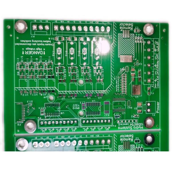
FR4 TG135 Double Layer PCB Board Immersion Gold
1 2 Layer FR4 substrate material printed circuit board.
2 Double layer copper, copper thickness is 35um/35um.
3 Finished pcb thickness is 0.8 mm.
4 Surface Treatment is immersion gold 1u'.
5 Used in consumer products.
6 2 layer pcb with 8/8mil min line space and width.
7 Green solder mask and white silkscreen.
8 Need customer to send us the gerber file or PCB file
NO | Item | Capability |
1 | Layer Count | 1-24 Layers |
2 | Board Thickness | 0.1mm-6.0mm |
3 | Finished Board Max Size | 700mm*800mm |
4 | Finished Board Thickness Tolerance | +/-10% +/-0.1(<1.0mm) |
5 | Warp | <0.7% |
6 | Major CCL Brand | KB/NanYa/ITEQ/ShengYi/Rogers Etc |
7 | Material Type | FR4,CEM-1,CEM-3,Aluminum,Copper, Ceramic, PI, PET |
8 | Drill Hole Diameter | 0.1mm-6.5mm |
9 | Out Layer Copper Thickness | 1/2OZ-8OZ |
10 | Inner Layer Copper Thickness | 1/3OZ-6OZ |
11 | Aspect Ratio | 10:1 |
12 | PTH Hole Tolerance | +/-3mil |
13 | NPTH Hole Tolerance | +/-1mil |
14 | Copper Thickness of PTH Wall | >10mil(25um) |
15 | Line Width And Space | 2/2mil |
16 | Min Solder Mask Bridge | 2.5mil |
17 | Solder Mask Alignment Tolerance | +/-2mil |
18 | Dimension Tolerance | +/-4mil |
19 | Max Gold Thickness | 200u'(0.2mil) |
20 | Thermal Shock | 288℃, 10s, 3 times |
21 | Impedance Control | +/-10% |
22 | Test Capability | PAD Size min 0.1mm |
23 | Min BGA | 7mil |
24 | Surface Treatment | OSP, ENIG,HASL, Plating Gold, Carbon Oil,Peelable Mask etc |
Q1: What is thermal resistance? How can the thermal resistance of a PCB be reduced?
A1: Thermal Resistance is a property of a printed circuit board that specifies its resistance to heat dispersion. A low thermal resistance in a PCB makes the dispersion of heat easier. This is basically the inverse of thermal conductivity. The thermal resistance of a PCB can be calculated by evaluating all the layers of the board and the heat parameters of the material.
To find the total thermal resistance for your board, you must include all layers of the board and the associated heat parameters for the type of material through which heat will flow.
[Formula]
R_theta = absolute thermal resistance (K/W) across the thickness of the sample
Delta x = thickness (m) of the sample (measured on a path parallel to the heat flow)
k = thermal conductivity (W/(K·m)) of the sample
A = cross-sectional area (m2) perpendicular to the path of heat flow
In addition to the thermal resistance of the board. The Thermal resistance of Vias must also be calculated. This usually depends on the copper trance, the laminate and the substrate and their respective thermal resistivities.
How can you reduce the Thermal Resistance of a PCB?