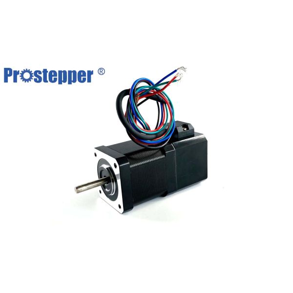
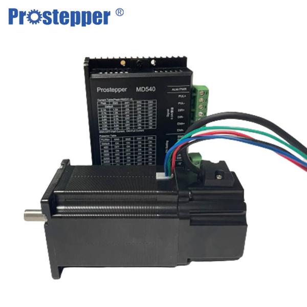
NEMA23 1.8 Degree Stepping Motor Brake Stepper Motor With Encoder 57*55mm For data product
Specifications
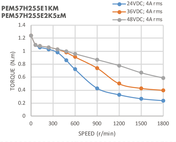
Holding Torque | 1.2N.m |
Related Current | 4A/Phase |
Resistance | 0.45Ω/Phase |
Inductance | 1.4MH/Phase |
Inertia | 280g.cm² |
Index | √ |
Output | Differental |
Black Torque | 1.3N.m |
Encoder Specifications Brake Specifications
Model | E1K | E2k5z | Model | PEM57/PEM60 |
Resolution | 1000cpr/4000ppr | 2500cpr/10000ppr | Brake Type | Holding Brake |
Type | Incremental encoder | Incremental encoder | Voltage | 24VDC±5% |
Output Mode | Differental | Differental | Power | 5W |
Output Signal | A+A-;B+B- | A+A-;B+B-;Z+Z- | Torque | 1.3N.m |
Supple Voltage | 5VDC±5% | 5VDC±5% | Release Time | 50ms |


Product description of 2 phase hybrid brake stepper motor
The rotational speed of the stepping motor can be precisely controlled ,By controlling the frequency of the electric pulse.
- The material is selected from well-known manufacturers at home and abroad. The advantages are light weight, good heat dissipation performance, good thermal conductivity, die-casting, good plasticity, higher elongation than iron, low noise, good motion stability, the disadvantages are high price, low hardness
- Online testing of technical parameters to ensure the consistency of data product parameters
- Material quality: The coat is 304 stainless steel, the water jacket is the high compression casting aluminum tube, the red copper coil.
- Electromagnetic furnace optimization design, lift torque, reduce temperature rise, so that the motor running smoothly
Features:
- high precision
- high torque
- durable
- medium size
- Stepping Accuracy: ± 5%
- Resistance Accuracy: ± 10%
- Inductance Accuracy: ± 20%
- Temperature Rise: 80°C Max.
- Ambient Temperature: -20°C ... +50°C
- Insulation Resistance: 100MOhm min. 500V DC
- Withstand: 500V AC, 1 Minute
Working principle of stepper motor
- To make the motor shaft turn, first one electromagnet is given power, which makes the gear’s teeth magnetically attracted to the electromagnet’s teeth. The point when the gear’s teeth are thus aligned to the first electromagnet, they are slightly offset from the next electromagnet. So when the next electromagnet is turned ON and the first is turned OFF, the gear rotates slightly to align with the next one and from there the process is repeated. Each of those slight rotations is called a step, with an integer number of steps making a full rotation. In that way, the motor can be turned by a precise. Stepper motor doesn’t rotate continuously, they rotate in steps. There are 4 coils with a 90o angle between each other fixed on the stator. The stepper motor connections are determined by the way the coils are interconnected. In a stepper motor, the coils are not connected. The motor has a 90o rotation step with the coils being energized in a cyclic order, determining the shaft rotation direction. The working of this motor is shown by operating the switch. The coils are activated in series in 1-sec intervals. The shaft rotates 90o each time the next coil is activated. Its low-speed torque will vary directly with current.