60V 72V PPTC resettable fuse 60V-005 60V-010 60V-020 60V-025 72V-030 72V-040 and more
Lead-free and halogen-free environmental protection products meet the ROHS(2011/65/EU) HF(EN14582) detection standard. Scope of application: widely used in various electronic products.
Product features: low voltage, low current, low resistance, short trip time, working current: 0.05A~4.00A
Working voltage: 60.0VDC
Working environment temperature: -40℃~85℃ Safety certification: UL pending.

| model | Working electricity press | Maximum electricity flow | Maintain electricity flow | Tripping electricity flow | consumed work rate | Maximum current trip time | Resistance range |
| V max | Imax | I hold | I trip | Pd | electric current | time | Rimin | Rimax | R1max |
| (Vdc) | (A) | (A) | (A) | (W) | (A) | (Sec) | (W) | (W) | (W) |
| 60R005 | 60 | 40 | 0.05 | 0.10 | 0.30 | 0.25 | 5.0 | 16.0 | 26.0 | 30.0 |
| 60R010 | 60 | 40 | 0.10 | 0.20 | 0.38 | 0.50 | 4.0 | 2.50 | 4.50 | 6.00 |
| 60R017 | 60 | 40 | 0.17 | 0.34 | 0.48 | 0.85 | 3.0 | 2.00 | 3.20 | 4.50 |
| 60R020 | 60 | 40 | 0.20 | 0.40 | 0.41 | 1.00 | 2.2 | 1.50 | 2.84 | 3.80 |
| 60R025 | 60 | 40 | 0.25 | 0.50 | 0.45 | 1.25 | 2.5 | 1.00 | 1.95 | 2.80 |
| 60R030 | 60 | 40 | 0.30 | 0.60 | 0.49 | 1.50 | 3.0 | 0.76 | 1.36 | 1.80 |
| 60R040 | 60 | 40 | 0.40 | 0.80 | 0.56 | 2.00 | 3.8 | 0.52 | 0.86 | 1.10 |
| 60R050 | 60 | 40 | 0.50 | 1.00 | 0.77 | 2.50 | 4.0 | 0.41 | 0.77 | 1.00 |
| 60R065 | 60 | 40 | 0.65 | 1.30 | 0.88 | 3.25 | 5.3 | 0.27 | 0.48 | 0.60 |
| 60R075 | 60 | 40 | 0.75 | 1.50 | 0.92 | 3.75 | 6.3 | 0.28 | 0.40 | 0.63 |
| 60R090 | 60 | 40 | 0.90 | 1.80 | 0.99 | 4.50 | 7.2 | 0.14 | 0.31 | 0.42 |
| 60R110 | 60 | 40 | 1.10 | 2.20 | 1.50 | 5.50 | 8.2 | 0.14 | 0.25 | 0.33 |
| 60R135 | 60 | 40 | 1.35 | 2.70 | 1.70 | 6.75 | 9.6 | 0.12 | 0.19 | 0.26 |
| 60R160 | 60 | 40 | 1.60 | 3.20 | 1.90 | 8.00 | 11.4 | 0.09 | 0.14 | 0.19 |
| 60R185 | 60 | 40 | 1.85 | 3.70 | 2.10 | 9.25 | 12.6 | 0.08 | 0.12 | 0.16 |
| 60R250 | 60 | 40 | 2.50 | 5.00 | 2.50 | 12.50 | 15.6 | 0.05 | 0.09 | 0.13 |
| 60R300 | 60 | 40 | 3.00 | 6.00 | 2.80 | 15.00 | 19.8 | 0.04 | 0.06 | 0.09 |
| 60R375 | 60 | 40 | 3.75 | 7.50 | 3.20 | 18.75 | 24.0 | 0.03 | 0.05 | 0.08 |
| 60R400 | 60 | 40 | 4.00 | 8.00 | 3.20 | 20 | 20 | 0.014 | 0.038 | 0.06 |
V max = the maximum voltage that the component can withstand under the rated current. I max = the maximum current that the component can withstand under the rated voltage.
I hold = the maximum current when the product does not move in the static air environment at 25℃. I trip = the minimum operating current in the static air environment at 25℃.
Pd = the power consumption of the product in the action state in the static air environment at 25℃. Rimin/max = the initial resistance at 25℃ (before welding).
R1max = the maximum resistance after welding for one hour at 25℃.
Caution: Operation beyond the specified rating may result in damage and arc and flame.
Holding current (I hold) values of PPTC at different ambient temperatures.
| model | operating ambient temperature |
| -40°C | -20°C | 0°C | 25°C | 40°C | 50°C | 60°C | 70°C | 85°C |
| 60R005 | 0.080 | 0.070 | 0.060 | 0.050 | 0.040 | 0.035 | 0.030 | 0.025 | 0.020 |
| 60R010 | 0.16 | 0.14 | 0.12 | 0.10 | 0.08 | 0.07 | 0.06 | 0.05 | 0.04 |
| 60R017 | 0.26 | 0.23 | 0.20 | 0.17 | 0.14 | 0.12 | 0.11 | 0.09 | 0.07 |
| 60R020 | 0.31 | 0.27 | 0.24 | 0.20 | 0.16 | 0.14 | 0.13 | 0.11 | 0.08 |
| 60R025 | 0.39 | 0.34 | 0.30 | 0.25 | 0.20 | 0.18 | 0.16 | 0.14 | 0.10 |
| 60R030 | 0.47 | 0.41 | 0.36 | 0.30 | 0.24 | 0.22 | 0.19 | 0.16 | 0.12 |
| 60R040 | 0.62 | 0.54 | 0.48 | 0.40 | 0.32 | 0.29 | 0.25 | 0.22 | 0.16 |
| 60R050 | 0.78 | 0.68 | 0.60 | 0.50 | 0.41 | 0.36 | 0.32 | 0.27 | 0.20 |
| 60R065 | 1.01 | 0.88 | 0.77 | 0.65 | 0.53 | 0.47 | 0.41 | 0.35 | 0.26 |
| 60R075 | 1.16 | 1.02 | 0.89 | 0.75 | 0.61 | 0.54 | 0.47 | 0.41 | 0.30 |
| 60R090 | 1.40 | 1.22 | 1.07 | 0.90 | 0.73 | 0.65 | 0.57 | 0.49 | 0.36 |
| 60R110 | 1.71 | 1.50 | 1.31 | 1.10 | 0.89 | 0.79 | 0.69 | 0.59 | 0.44 |
| 60R135 | 2.09 | 1.84 | 1.61 | 1.35 | 1.09 | 0.97 | 0.85 | 0.73 | 0.54 |
| 60R160 | 2.48 | 2.18 | 1.90 | 1.60 | 1.30 | 1.15 | 1.01 | 0.86 | 0.64 |
| 60R185 | 2.87 | 2.52 | 2.20 | 1.85 | 1.50 | 1.33 | 1.17 | 1.00 | 0.74 |
| 60R250 | 3.88 | 3.40 | 2.98 | 2.50 | 2.03 | 1.80 | 1.58 | 1.35 | 1.00 |
| 60R300 | 4.65 | 4.08 | 3.57 | 3.00 | 2.43 | 2.16 | 1.89 | 1.62 | 1.20 |
| 60R375 | 5.81 | 5.10 | 4.46 | 3.75 | 3.04 | 2.70 | 2.36 | 2.03 | 1.50 |
| 60R400 | 6.20 | 5.44 | 4.76 | 4.00 | 3.24 | 2.88 | 2.52 | 2.16 | 1.60 |
Product size specification (mm.)
Figure 1 Figure 2 Printing code
R = trademark
60= 60 Vrms working voltage
135 = 1.35A holding current
XXX= date Y= factory code
| model | A | B | C | D | E | pin | graph |
| Max. | Max. | Typ. | Min. | Max. | Line warp | wire rod |
| 60R005 | 5.7 | 10.5 | 3.1 | 7.6 | 5.1 | 0.50 | Tin - caoted copper - clad steel wire | Figure 2 |
| 60R010 | 5.7 | 10.5 | 3.1 | 7.6 | 5.1 | 0.50 | Tin - caoted copper - clad steel wire | figure 1 |
| 60R017 | 5.9 | 11.2 | 3.1 | 7.6 | 5.1 | 0.50 | Tin - caoted copper - clad steel wire | figure 1 |
| 60R020 | 5.9 | 11.2 | 3.1 | 7.6 | 5.1 | 0.50 | Tin - caoted copper - clad steel wire | figure 1 |
| 60R025 | 6.1 | 11.4 | 3.1 | 7.6 | 5.1 | 0.50 | Tin - caoted copper - clad steel wire | figure 1 |
| 60R030 | 7.6 | 13.4 | 3.1 | 7.6 | 5.1 | 0.50 | Tin - caoted copper - clad steel wire | figure 1 |
| 60R040 | 7.7 | 13.6 | 3.1 | 7.6 | 5.1 | 0.50 | Tin - caoted copper - clad steel wire | figure 1 |
| 60R050 | 7.9 | 13.7 | 3.1 | 7.6 | 5.1 | 0.50 | Tin - caoted copper - clad steel wire | figure 1 |
| 60R065 | 9.7 | 14.5 | 3.1 | 7.6 | 5.1 | 0.60 | Tin - caoted copper - clad steel wire | figure 1 |
| 60R075 | 10.7 | 15.5 | 3.1 | 7.6 | 5.1 | 0.60 | Tin - caoted copper - clad steel wire | figure 1 |
| 60R090 | 11.7 | 16.5 | 3.1 | 7.6 | 5.1 | 0.60 | Tin - caoted copper - clad steel wire | figure 1 |
| 60R110 | 13.0 | 16.7 | 3.1 | 7.6 | 5.1 | 0.80 | Tin - caoted copper - clad steel wire | Figure 2 |
| 60R135 | 15.7 | 17.6 | 3.1 | 7.6 | 5.1 | 0.80 | Tin - caoted copper - clad steel wire | Figure 2 |
| 60R160 | 16.7 | 19.7 | 3.1 | 7.6 | 5.1 | 0.80 | Tin - caoted copper - clad steel wire | Figure 2 |
| 60R185 | 17.8 | 22.9 | 3.1 | 7.6 | 5.1 | 0.80 | Tin - caoted copper - clad steel wire | Figure 2 |
| 60R250 | 21.3 | 23.5 | 3.1 | 7.6 | 10.2 | 0.80 | tinned wird | Figure 2 |
| 60R300 | 24.9 | 27.4 | 3.1 | 7.6 | 10.2 | 0.80 | tinned wird | Figure 2 |
| 60R375 | 28.5 | 32.5 | 3.1 | 7.6 | 10.2 | 0.80 | tinned wird | Figure 2 |
| 60R400 | 21 | 26 | 3.1 | 7.6 | 10.2 | 0.80 | tinned wird | Figure 2 |
Solderability of lead: MIL-STD-202, method 208E.
Product: The product label is marked with logo, rated current, rated voltage and date code.
Numb
R = trademark
60= 60 Vrms working voltage
135 = 1.35A holding current
XXX= date Y= factory code
| model | A | B | C | D | E | pin | graph |
| Max. | Max. | Typ. | Min. | Max. | Line warp | wire rod |
| 60R005 | 5.7 | 10.5 | 3.1 | 7.6 | 5.1 | 0.50 | Tin - caoted copper - clad steel wire | Figure 2 |
| 60R010 | 5.7 | 10.5 | 3.1 | 7.6 | 5.1 | 0.50 | Tin - caoted copper - clad steel wire | figure 1 |
| 60R017 | 5.9 | 11.2 | 3.1 | 7.6 | 5.1 | 0.50 | Tin - caoted copper - clad steel wire | figure 1 |
| 60R020 | 5.9 | 11.2 | 3.1 | 7.6 | 5.1 | 0.50 | Tin - caoted copper - clad steel wire | figure 1 |
| 60R025 | 6.1 | 11.4 | 3.1 | 7.6 | 5.1 | 0.50 | Tin - caoted copper - clad steel wire | figure 1 |
| 60R030 | 7.6 | 13.4 | 3.1 | 7.6 | 5.1 | 0.50 | Tin - caoted copper - clad steel wire | figure 1 |
| 60R040 | 7.7 | 13.6 | 3.1 | 7.6 | 5.1 | 0.50 | Tin - caoted copper - clad steel wire | figure 1 |
| 60R050 | 7.9 | 13.7 | 3.1 | 7.6 | 5.1 | 0.50 | Tin - caoted copper - clad steel wire | figure 1 |
| 60R065 | 9.7 | 14.5 | 3.1 | 7.6 | 5.1 | 0.60 | Tin - caoted copper - clad steel wire | figure 1 |
| 60R075 | 10.7 | 15.5 | 3.1 | 7.6 | 5.1 | 0.60 | Tin - caoted copper - clad steel wire | figure 1 |
| 60R090 | 11.7 | 16.5 | 3.1 | 7.6 | 5.1 | 0.60 | Tin - caoted copper - clad steel wire | figure 1 |
| 60R110 | 13.0 | 16.7 | 3.1 | 7.6 | 5.1 | 0.80 | Tin - caoted copper - clad steel wire | Figure 2 |
| 60R135 | 15.7 | 17.6 | 3.1 | 7.6 | 5.1 | 0.80 | Tin - caoted copper - clad steel wire | Figure 2 |
| 60R160 | 16.7 | 19.7 | 3.1 | 7.6 | 5.1 | 0.80 | Tin - caoted copper - clad steel wire | Figure 2 |
| 60R185 | 17.8 | 22.9 | 3.1 | 7.6 | 5.1 | 0.80 | Tin - caoted copper - clad steel wire | Figure 2 |
| 60R250 | 21.3 | 23.5 | 3.1 | 7.6 | 10.2 | 0.80 | tinned wird | Figure 2 |
| 60R300 | 24.9 | 27.4 | 3.1 | 7.6 | 10.2 | 0.80 | tinned wird | Figure 2 |
| 60R375 | 28.5 | 32.5 | 3.1 | 7.6 | 10.2 | 0.80 | tinned wird | Figure 2 |
| 60R400 | 21 | 26 | 3.1 | 7.6 | 10.2 | 0.80 | tinned wird | Figure 2 |
Solderability of lead: MIL-STD-202, method 208E.
Product: The product label is marked with logo, rated current, rated voltage and date code.
er of packages
| Order information | | | | Packing | | |
| 60 | 185 | K or S | R or U | Model | Reel Q'ty | Bag Q'ty |
| Radial type | Hold | K=Kink leads | R= Tape & | 60R010 ~ 60R090 | 3000 | 500 |
| 60 V | Current | | Reel | 60R017 | 2500 | 500 |
| | (A) | S=Straight | U= Bulk | 60R110 ~ 60R185 | 1500 | 500 |
| | | leads | packaged | 60R250 ~ 60R375 | - | 500 |
Tape and reel packaging per eia468-b standard.
respectfully inform
- Exceeding the applicable conditions of this product or other improper use may cause damage, and may even cause electric breakdown or flame.
- This product is designed for the occasional overcurrent in the circuit, and it is not recommended to be used in the circuit with repeated overcurrent in a short time.
- This product avoids long-term contact with chemical solvents.
Lead-free and halogen-free environmental protection products meet the ROHS(2011/65/EU) HF(EN14582) detection standard. Scope of application: widely used in various electronic products.
Product features: low voltage, low current, low resistance, short trip time, working current: 0.05A~4.00A
Operating voltage: 72.0VDC
Working environment temperature: -40℃~85℃ Safety certification: UL pending.
| model | Working electricity press | Maximum electricity flow | Maintain electricity flow | Tripping electricity flow | consumed work rate | Maximum current trip time | Resistance range |
| V max | Imax | I hold | I trip | Pd | electric current | time | Rimin | Rimax | R1max |
| (Vdc) | (A) | (A) | (A) | (W) | (A) | (Sec) | (W) | (W) | (W) |
| 72R020 | seventy-two | 40 | 0.20 | 0.40 | 0.41 | 1.00 | 2.2 | 1.50 | 2.84 | 3.80 |
| 72R025 | seventy-two | 40 | 0.25 | 0.50 | 0.45 | 1.25 | 2.5 | 1.00 | 1.95 | 2.80 |
| 72R030 | seventy-two | 40 | 0.30 | 0.60 | 0.49 | 1.50 | 3.0 | 0.76 | 1.36 | 1.80 |
| 72R040 | seventy-two | 40 | 0.40 | 0.80 | 0.56 | 2.00 | 3.8 | 0.52 | 0.86 | 1.10 |
| 72R050 | seventy-two | 40 | 0.50 | 1.00 | 0.77 | 2.50 | 4.0 | 0.41 | 0.77 | 1.00 |
| 72R065 | seventy-two | 40 | 0.65 | 1.30 | 0.88 | 3.25 | 5.3 | 0.27 | 0.48 | 0.60 |
| 72R075 | seventy-two | 40 | 0.75 | 1.50 | 0.92 | 3.75 | 6.3 | 0.28 | 0.40 | 0.63 |
| 72R090 | seventy-two | 40 | 0.90 | 1.80 | 0.99 | 4.50 | 7.2 | 0.14 | 0.31 | 0.42 |
| 72R110 | seventy-two | 40 | 1.10 | 2.20 | 1.50 | 5.50 | 8.2 | 0.14 | 0.25 | 0.33 |
| 72R135 | seventy-two | 40 | 1.35 | 2.70 | 1.70 | 6.75 | 9.6 | 0.12 | 0.19 | 0.26 |
| 72R160 | seventy-two | 40 | 1.60 | 3.20 | 1.90 | 8.00 | 11.4 | 0.09 | 0.14 | 0.19 |
| 72R185 | seventy-two | 40 | 1.85 | 3.70 | 2.10 | 9.25 | 12.6 | 0.08 | 0.12 | 0.16 |
| 72R250 | seventy-two | 40 | 2.50 | 5.00 | 2.50 | 12.50 | 15.6 | 0.05 | 0.09 | 0.13 |
| 72R300 | seventy-two | 40 | 3.00 | 6.00 | 2.80 | 15.00 | 19.8 | 0.04 | 0.06 | 0.09 |
| 72R375 | seventy-two | 40 | 3.75 | 7.50 | 3.20 | 18.75 | 24.0 | 0.03 | 0.05 | 0.08 |
| 72R400 | seventy-two | 40 | 4.00 | 8.00 | 3.20 | 20 | 20 | 0.014 | 0.038 | 0.06 |
V max = the maximum voltage that the component can withstand under the rated current. I max = the maximum current that the component can withstand under the rated voltage.
I hold = the maximum current when the product does not move in the static air environment at 25℃. I trip = the minimum operating current in the static air environment at 25℃.
Pd = the power consumption of the product in the action state in the static air environment at 25℃. Rimin/max = the initial resistance at 25℃ (before welding).
R1max = the maximum resistance after welding for one hour at 25℃.
Caution: Operation beyond the specified rating may result in damage and arc and flame.
Holding current (I hold) value of PPTC at different ambient temperatures.
| model | operating ambient temperature |
| -40°C | -20°C | 0°C | 25°C | 40°C | 50°C | 60°C | 70°C | 85°C |
| 72R020 | 0.31 | 0.27 | 0.24 | 0.20 | 0.16 | 0.14 | 0.13 | 0.11 | 0.08 |
| 72R025 | 0.39 | 0.34 | 0.30 | 0.25 | 0.20 | 0.18 | 0.16 | 0.14 | 0.10 |
| 72R030 | 0.47 | 0.41 | 0.36 | 0.30 | 0.24 | 0.22 | 0.19 | 0.16 | 0.12 |
| 72R040 | 0.62 | 0.54 | 0.48 | 0.40 | 0.32 | 0.29 | 0.25 | 0.22 | 0.16 |
| 72R050 | 0.78 | 0.68 | 0.60 | 0.50 | 0.41 | 0.36 | 0.32 | 0.27 | 0.20 |
| 72R065 | 1.01 | 0.88 | 0.77 | 0.65 | 0.53 | 0.47 | 0.41 | 0.35 | 0.26 |
| 72R075 | 1.16 | 1.02 | 0.89 | 0.75 | 0.61 | 0.54 | 0.47 | 0.41 | 0.30 |
| 72R090 | 1.40 | 1.22 | 1.07 | 0.90 | 0.73 | 0.65 | 0.57 | 0.49 | 0.36 |
| 72R110 | 1.71 | 1.50 | 1.31 | 1.10 | 0.89 | 0.79 | 0.69 | 0.59 | 0.44 |
| 72R135 | 2.09 | 1.84 | 1.61 | 1.35 | 1.09 | 0.97 | 0.85 | 0.73 | 0.54 |
| 72R160 | 2.48 | 2.18 | 1.90 | 1.60 | 1.30 | 1.15 | 1.01 | 0.86 | 0.64 |
| 72R185 | 2.87 | 2.52 | 2.20 | 1.85 | 1.50 | 1.33 | 1.17 | 1.00 | 0.74 |
| 72R250 | 3.88 | 3.40 | 2.98 | 2.50 | 2.03 | 1.80 | 1.58 | 1.35 | 1.00 |
| 72R300 | 4.65 | 4.08 | 3.57 | 3.00 | 2.43 | 2.16 | 1.89 | 1.62 | 1.20 |
| 72R375 | 5.81 | 5.10 | 4.46 | 3.75 | 3.04 | 2.70 | 2.36 | 2.03 | 1.50 |
| 72R400 | 6.20 | 5.44 | 4.76 | 4.00 | 3.24 | 2.88 | 2.52 | 2.16 | 1.60 |
R = trademark
72= 72 Vrms working voltage
135 = 1.35A holding current
XXX= date Y= factory code
| model | A | B | C | D | E | pin | graph |
| Max. | Max. | Typ. | Min. | Max. | Line warp | wire rod |
| 72R020 | 5.9 | 11.2 | 3.1 | 7.6 | 5.1 | 0.50 | Tin - caoted copper - clad steel wire | figure 1 |
| 72R025 | 6.1 | 11.4 | 3.1 | 7.6 | 5.1 | 0.50 | Tin - caoted copper - clad steel wire | figure 1 |
| 72R030 | 7.6 | 13.4 | 3.1 | 7.6 | 5.1 | 0.50 | Tin - caoted copper - clad steel wire | figure 1 |
| 72R040 | 7.7 | 13.6 | 3.1 | 7.6 | 5.1 | 0.50 | Tin - caoted copper - clad steel wire | figure 1 |
| 72R050 | 7.9 | 13.7 | 3.1 | 7.6 | 5.1 | 0.50 | Tin - caoted copper - clad steel wire | figure 1 |
| 72R065 | 9.7 | 14.5 | 3.1 | 7.6 | 5.1 | 0.60 | Tin - caoted copper - clad steel wire | figure 1 |
| 72R075 | 10.7 | 15.5 | 3.1 | 7.6 | 5.1 | 0.60 | Tin - caoted copper - clad steel wire | figure 1 |
| 72R090 | 11.7 | 16.5 | 3.1 | 7.6 | 5.1 | 0.60 | Tin - caoted copper - clad steel wire | figure 1 |
| 72R110 | 13.0 | 16.7 | 3.1 | 7.6 | 5.1 | 0.80 | Tin - caoted copper - clad steel wire | Figure 2 |
| 72R135 | 15.7 | 17.6 | 3.1 | 7.6 | 5.1 | 0.80 | Tin - caoted copper - clad steel wire | Figure 2 |
| 72R160 | 16.7 | 19.7 | 3.1 | 7.6 | 5.1 | 0.80 | Tin - caoted copper - clad steel wire | Figure 2 |
| 72R185 | 17.8 | 22.9 | 3.1 | 7.6 | 5.1 | 0.80 | Tin - caoted copper - clad steel wire | Figure 2 |
| 72R250 | 21.3 | 23.5 | 3.1 | 7.6 | 10.2 | 0.80 | tinned wird | Figure 2 |
| 72R300 | 24.9 | 27.4 | 3.1 | 7.6 | 10.2 | 0.80 | tinned wird | Figure 2 |
| 72R375 | 28.5 | 32.5 | 3.1 | 7.6 | 10.2 | 0.80 | tinned wird | Figure 2 |
| 72R400 | 21 | 26 | 3.1 | 7.6 | 10.2 | 0.80 | tinned wird | Figure 2 |
Solderability of lead: MIL-STD-202, method 208E.
Product: The product label is marked with logo, rated current, rated voltage and date code.
Number of packages
| Order information | | | | Packing | | |
| seventy-two | 185 | K or S | R or U | Model | Reel Q'ty | Bag Q'ty |
| Radial type | Hold | K=Kink leads | R= Tape & | 72R010 ~ 72R090 | 3000 | 500 |
| 72 V | Current | | Reel | 72R017 | 2500 | 500 |
| | (A) | S=Straight | U= Bulk | 72R110 ~ 72R185 | 1500 | 500 |
| | | leads | packaged | 72R250 ~ 72R375 | - | 500 |
Tape and reel packaging per eia468-b standard.
respectfully inform
- Exceeding the applicable conditions of this product or other improper use may cause damage, and may even cause electric breakdown or flame.
- This product is designed for the occasional overcurrent in the circuit, and it is not recommended to be used in the circuit with repeated overcurrent in a short time.
- This product avoids long-term contact with chemical solvents.
Product Description:
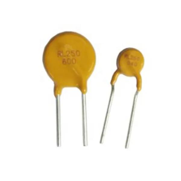
Introducing the Polymer Positive Temperature Coefficient (PPTC) Thermistor Device – the ideal device for protecting against over-current and over-voltage conditions. This PPTC Thermistor Device is designed to be compact, measuring just 5.1mm in size, and is rated for up to 250V. It features a trip current of 0.1A and is available in a bright yellow color. Additionally, the PPTC Thermistor Device has a high max impulse voltage of 250V, making it a reliable and safe choice for protecting electrical circuits from over-current and over-voltage conditions.
The PPTC Thermistor Device is an essential piece of equipment for any electrical circuit. Thanks to its small size and high max impulse voltage, it can provide the reliable protection that any circuit needs, while also maintaining its compact form factor. The PPTC Thermistor Device is the perfect choice for any application that requires reliable protection against over-current and over-voltage conditions.
Features:
- Polymer Positive Temperature Coefficient Thermistor Device (PPTC Thermistor)
- Max Voltage: 60V
- Rated Voltage: 250V
- Trip Current: 0.1A
- Hold Current: 0.05A
Technical Parameters:
| Product Name | PPTC Thermistor |
| Max Voltage | 60V |
| Color | Yellow |
| Max Impulse Voltage | 250V |
| Size (Max) | 5.1mm |
| Trip Current | 0.1A |
| Hold Current | 0.05A |
| Rated Voltage | 250V |
| Max Current | 3A |
| Product Description | Polymer-Positive-Temperature-Coefficient Thermistor, PPTC Thermistor Device, Polymer Positive Temperature Coefficient Thermistor Device |
Applications:
PPTC Thermistor Devices, developed by LINKUN, are polymer-positive-temperature-coefficient (PPTC) thermistors with a resettable fuse of 250V 1A. The product has an origin of Dongguan, Guangdong, China and is a max size of 5.1mm with a max voltage of 60V. It comes in a bright yellow color and is named PTC Resettable PPTC 250V 050-5A.
This PPTC Thermistor Device is perfect for a range of applications and scenarios. It can be used whenever a reliable over-current protection and resettable fuse is needed, such as in a variety of consumer electronic products, including power supplies, battery packs, LED lighting, and medical devices. The PPTC Thermistor Device is also ideal for use in automotive applications, such as in DC/DC converters, power inverters, and on-board power supplies.
The PPTC Thermistor Device is the perfect solution for any project or application that requires a reliable and safe over-current protection and resettable fuse. With its superior temperature coefficient, LINKUN’s PPTC Thermistor Device is the perfect solution for any project that requires a reliable and safe over-current protection and resettable fuse.
Customization:
Customized PPTC Thermistor Service from LINKUN
LINKUN offers customized Polymer Positive Temperature Coefficient Thermistor Device (PPTC Thermistor Device) services, with the following product attributes:
- Brand Name: LINKUN
- Model Number: PPTC resettable fuse 250V 1A
- Place of Origin: Dongguan, Guangdong, China
- Rated Voltage: 250V
- Max Voltage: 60V
- Size (Max): 5.1mm
- Hold Current: 0.05A
- Product Name: PTC Resettable PPTC 250V 050-5A
We focus on providing high-quality PPTC thermistor device services, and we strive to provide the best customer service available. Our customers are our top priority, and we look forward to working with you to create the perfect PPTC thermistor device for your needs.
Support and Services:
PPTC Thermistor provides technical support and services to ensure that customers get the most out of their product. Our team of knowledgeable and experienced engineers is available to provide assistance with product selection, installation, operation, programming, and troubleshooting. Our technical support staff can provide detailed advice and guidance on product performance, specifications, and design parameters, as well as on other issues related to the operation of PPTC Thermistor products.
We also offer comprehensive product warranty and repair services, as well as preventive maintenance and spare parts support. Our warranty policy covers all parts and labor needed to repair or replace any defective product, as well as all necessary components and replacement parts for the product. We also offer a 24-hour emergency service hotline to ensure that customers have timely access to our experts in the event of an urgent issue.
For more information on PPTC Thermistor's technical support and services, please contact our customer service department at +1 (123) 456-7890.
Packing and Shipping:
PPTC Thermistor Packaging and Shipping:
- All PPTC Thermistor products will be packaged in sealed plastic bags.
- PPTC Thermistor will be shipped via air mail or express courier.
- All PPTC Thermistor products must be checked for quality and accuracy before being shipped.
- The customer is responsible for any applicable taxes or duties that may be charged by the receiving country.
FAQ:
Q: What is PPTC Thermistor? A: PPTC Thermistor is a type of Polymeric Positive Temperature Coefficient resistors that are used to protect electronic circuits from overcurrent.
Q: What is the brand name of PPTC Thermistor? A: The brand name of PPTC Thermistor is LINKUN.
Q: What is the model number of PPTC Thermistor? A: The model number of PPTC Thermistor is PPTC resettable fuse 250V 1A.
Q: Where is PPTC Thermistor manufactured? A: PPTC Thermistor is manufactured in Dongguan, Guangdong, China.
Q: What are the applications of PPTC Thermistor? A: PPTC Thermistor is commonly used for protection in wide range of consumer electronics such as computers, power supplies, audio-visual equipment, and telecommunications equipment.