High Power NTC Thermistor MF73T Series MF73T-1 5/14 Surge Protection For Switching Power Supply
High-power NTC thermistor MF73T series
R25(Ω): 0.2~400 Imax(A):40A
[Product features] Small size, high power, strong surge current suppression capability
[Product use] High-power switching power supply, conversion power supply, UPS power supply
Features
● Small size, high power, strong surge current suppression capability.
● Large material constant (B value), small residual resistance, low power consumption.
● High current, long life, high reliability.
● Easy to install on circuit boards, full series, wide application range.
Inrush current is the momentary surge of current created when power is turned on to motors, transformers, power suppliers and heating elements. The more power required by industrial equipment,the larger the inrush current. It can effectively quench the inrush current by means of in series with power NTC thermistor in return circuit of power supply. The thermistor’s resistance decreases dramatically following the inrush, allowing the steady state curent to flow with very little resistance.This effect provides inrush current protection, yet allows efficiency during normal operation.The power NTC Thermistor produced by Guangdong Uchi Technology Co.,Ltd. with large scale,especially MF73T, MF73, MF74, MF75 serial products with big size, which can be applied in such inrush protection with industrial level as industrial robots and automation.
NTC negative temperature coefficient thermistor temperature range
Its measurement range is generally -10~+300℃, and it can also be -200~+10℃, and it can even be used for temperature measurement in the environment of +300~+1200℃.
The accuracy of the negative temperature coefficient thermistor thermometer can reach 0.1 ℃, and the temperature sensing time can be as little as 10s or less. It is not only suitable for granary thermometers, but also can be used for temperature measurement in food storage, medicine and health, scientific farming, oceans, deep wells, high altitudes, glaciers, etc.
NTC thermistors are divided into:
Power type NTC thermistor
Compensated NTC Thermistor
Temperature measuring NTC thermistor
Main features of NTC thermistor:
1. High sensitivity, usually the resistance value changes by about 1%~6% when the temperature changes by 1°C, the range of the temperature coefficient of resistance is very wide, and the absolute value is 10~100 times larger than that of ordinary metal resistance;
2. The working temperature range is wide, the normal temperature device is suitable for -55°C ~ 315°C, the high temperature device is suitable for a temperature higher than 315°C (currently the highest can reach 2000°C), and the low temperature device is suitable for -273°C ~ -55°C;
3. Small in size, it can measure the temperature of gaps, cavities and blood vessels in living organisms that cannot be measured by other thermometers;
4. Easy to use, the resistance value can be freely selected between 0.1 ~ 100kΩ;
5. Rich raw material resources and low price; and easy to process into complex shapes, which can be mass-produced;
6. Good stability, strong overload capacity and good performance.
Can be installed into the power circuits of:
• Power supplies and inverters
• Uninterruptible Power Supplies
• Energy saving lamps
• Electronic Ballasts
• Filament Protection of various types of lamps
• Some types of heaters
• For higher power circuits ask about the MF73
and MF74 series surge suppressors.
| Material: | Synthetic Film | Power Characteristics: | Medium Power |
| Allow Tolerance: | ±10(%) | Shape: | Flat Sheet |
| Temperature Coefficient: | NTC |
| Frequency Characteristics: | Medium Frequency |

Part NO.
MF73T-1 | Res +20%
(Ω) | Max. Steady
State Current
lmax (A) | Approx. R
of MaxCurrent
Rmax (Ω) |
ø15mm Chip Diameter
Max Rated Power Pmax (W): 3.5
Dissipation Coefficient (mW/℃): ≥ 22
Thermal Time Constant (S): ≤ 75 |
| 1.3/10 | 1.3 | 10 | 0.034 |
| 1.5/10 | 1.5 | 10 | 0.036 |
| 2.5/9.5 | 2.5 | 9.5 | 0.044 |
| 5/8 | 5 | 8 | 0.058 |
| 6/7 | 6 | 7 | 0.069 |
| 7/7 | 7 | 7 | 0.078 |
| 8/7 | 8 | 7 | 0.084 |
| 10/7 | 10 | 7 | 0.098 |
| 12/6 | 12 | 6 | 0.116 |
| 15/6 | 16 | 6 | 0.129 |
| 20/6 | 20 | 6 | 0.136 |
| 30/5 | 30 | 5 | 0.165 |
| 47/4 | 47 | 4 | 0.257 |
| 120/2.5 | 120 | 2.5 | 0.652 |
Part NO.
MF73T-1 | Res +20%
(Ω) | Max. Steady
State Current
lmax (A) | Approx. R
of MaxCurrent
Rmax (Ω) |
ø20mm Chip Diameter
Max Rated Power Pmax (W): 5.0
Dissipation Coefficient (mW/℃): ≥ 28
Thermal Time Constant (S): ≤ 110 |
| 0.7/16 | 0.7 | 16 | 0.026 |
| 1/16 | 1 | 16 | 0.027 |
| 1.5/15 | 1.5 | 15 | 0.030 |
| 2/14 | 2 | 14 | 0.035 |
| 2.5/13 | 2.5 | 13 | 0.038 |
| 3/12 | 3 | 12 | 0.040 |
| 4/12 | 4 | 12 | 0.043 |
| 4.7/12 | 4.7 | 12 | 0.046 |
| 5/12 | 5 | 12 | 0.047 |
| 6/11 | 6 | 11 | 0.052 |
| 6.8/10 | 6.8 | 10 | 0.055 |
| 7/9 | 7 | 9 | 0.056 |
| 10/8 | 10 | 8 | 0.085 |
| 12/7.5 | 12 | 7.5 | 0.098 |
| 15/7 | 15 | 7 | 0.112 |
| 18/7 | 18 | 7 | 0.123 |
| 20/7 | 20 | 7 | 0.132 |
Part NO.
MF73T-1 | Res +20%
(Ω) | Max. Steady
State Current
lmax (A) | Approx. R
of MaxCurrent
Rmax (Ω) |
ø25mm Chip Diameter
Max Rated Power Pmax (W): 7.0
Dissipation Coefficient (mW/℃): ≥ 30
Thermal Time Constant (S): ≤ 130 |
| 0.5/22 | 0.5 | 22 | 0.017 |
| 0.7/22 | 0.7 | 22 | 0.017 |
| 1/20 | 1 | 20 | 0.021 |
| 1.5/19 | 1.5 | 19 | 0.024 |
| 2/18 | 2 | 18 | 0.026 |
| 2.5/16 | 2.5 | 16 | 0.029 |
| 3/15.5 | 3 | 15.5 | 0.032 |
| 4/15 | 4 | 15 | 0.039 |
| 4.7/14 | 4.7 | 14 | 0.044 |
| 5/14 | 5 | 14 | 0.047 |
| 6.8/12 | 6.8 | 12 | 0.061 |
| 7/11 | 7 | 11 | 0.064 |
| 8/10 | 8 | 10 | 0.079 |
| 10/10 | 10 | 10 | 0.084 |
| 12/9 | 12 | 9 | 0.102 |
| 15/8 | 15 | 8 | 0.117 |
| 18/8 | 18 | 8 | 0.132 |
| 20/8 | 20 | 8 | 0.132 |
Part NO.
MF73T-1 | Res +20%
(Ω) | Max. Steady
State Current
lmax (A) | Approx. R
of MaxCurrent
Rmax (Ω) |
ø30mm Chip Diameter
Max Rated Power Pmax (W): 8.0
Dissipation Coefficient (mW/℃): ≥ 40
Thermal Time Constant (S): ≤ 190 |
| 0.5/30 | 0.5 | 30 | 0.013 |
| 1/30 | 1 | 30 | 0.014 |
| 1.5/25 | 1.5 | 25 | 0.016 |
| 2/23 | 2 | 23 | 0.019 |
| 2.5/20 | 2.5 | 20 | 0.023 |
| 3/19.5 | 3 | 19.5 | 0.026 |
| 4/19 | 4 | 19 | 0.031 |
| 4.7/18 | 4.7 | 18 | 0.035 |
| 5/17 | 5 | 17 | 0.037 |
| 6.8/16 | 6.8 | 16 | 0.043 |
| 7/15 | 7 | 15 | 0.044 |
| 8/14 | 8 | 14 | 0.049 |
| 10/13 | 10 | 13 | 0.056 |
| 12/12 | 12 | 12 | 0.067 |
| 15/11 | 15 | 11 | 0.078 |
| 18/10 | 18 | 10 | 0.092 |
| 29/9 | 20 | 9 | 0.113
|
Part NO.
MF73T-1 | Res +20%
(Ω) | Max. Steady
State Current
lmax (A) | Approx. R
of MaxCurrent
Rmax (Ω) |
ø35mm Chip Diameter
Max Rated Power Pmax (W): 9.0
Dissipation Coefficient (mW/℃): ≥ 55
Thermal Time Constant (S): ≤ 280 |
| 0.5/32 | 0.5 | 32 | 0.01 |
| 1/32 | 1 | 32 | 0.011 |
| 1.5/28 | 1.5 | 28 | 0.013 |
| 2/25 | 2 | 25 | 0.017 |
| 2.5/23 | 2.5 | 23 | 0.020 |
| 3/22 | 3 | 22 | 0.023 |
| 4/21 | 4 | 21 | 0.026 |
| 4.7/20 | 4.7 | 20 | 0.029 |
| 5/19 | 5 | 19 | 0.030 |
| 6.8/18 | 6.8 | 18 | 0.035 |
| 7/17 | 7 | 17 | 0.037 |
| 8/16 | 8 | 16 | 0.041 |
| 10/15 | 10 | 15 | 0.045 |
| 12/14 | 12 | 14 | 0.051 |
| 15/13 | 15 | 13 | 0.060 |
| 18/11 | 18 | 11 | 0.072 |
| 20/10 | 20 | 10 | 0.089 |
MF72 Power NTC Thermistor
The main function of the MF72 series power NTC thermistor is to provide surge current suppression for sensitive electronics. Connecting the MF72 in series with the power supply will limit the current surge that is usually created when turning on. Once the circuit is powered on, the MF72 power NTC thermistor will quickly drop to a very low value, the power dissipation can be ignored and will not affect the normal operating current. Using the MF72 power NTC thermistor is one of the most cost-effective ways to suppress surge current and protect sensitive electronics from damage.
Applications:
• Can be installed in power circuits of:
• Power supplies and inverters
• Uninterruptible power supplies
• Energy-saving lamps
• Electronic ballasts
• Filament protection for various lamps
• Some types of heaters
• For higher power circuits compared to MF73 high power NTC thermistor
Product Features:
• Small size and fast response
• High power handling capability and long-term stability and reliability
• Fast response to surge current
• High material constant (B value)
• Low residual resistance
• Wide operating temperature range -55 to + 200C
• R25 tolerance of ±20%
Specifications and dimensions:
Specifications:
| DMAX | Dmax | Tmax | d | F1 | F2 | Straight Leads | Bend Leads |
| | | ±0.05 | ±1 | ±1.5 | Lmin | Lmin | L2±2 |
| MF72□D5 | 7 | 5 | 0.6 / 0.45 | 5 / 2.5 | 3 | 25 | 17/5.0 | 8/5.0 |
| MF72□D7 | 9 | 5 | 0.6 | 5 | 3 | 25 | 17/5.0 | 8/5.0 |
| MF72□D9 | 11 | 5.5 | 0.8 / 0.6 | 7.5 / 5 | 5/3 | 25 | 17/5.0 | 8/5.0 |
| MF72□D11 | 13 | 5.5 | 0.8 | 7.5 / 5 | 5/3 | 25 | 17/5.0 | 8/5.0 |
| MF72□D13 | 15.5 | 6 | 0.8 | 7.5 | 5 | 25 | 17/5.0 | 8/5.0 |
| MF72□D15 | 17.5 | 6 | 0.8 | 10 / 7.5 | 5 | 25 | 17/5.0 | 8/5.0 |
| MF72□D20 | 22.5 | 7 | 1 | 10 / 7.5 | / | 25 | / | / |
| MF72□D25 | 27.5 | 8 | 1 | 10 / 7.5 | / | 25 | / | / |
Main technical parameters:
| D-5 NTC Thermistor |
| Part Number MF72 NTC | R25 (Ω) | Max steady-state current(A) | Approximate resistance value at maximum current Ω) | Dissipation coefficient approx. (MW /℃) | Thermal time constant approx. (S) | Operating temperature (°C) | UL |
| 3D-5 | 3 | 1.3 | 0.177 | 7 | 16 | -40〜+ 150 | |
| 5D-5 | 5 | 1 | 0.353 | 7 | 16 | -40〜+ 150 | √ |
| 10D-5 | 10 | 0.7 | 0.771 | 7 | 16 | -40〜+ 150 | √ |
| 20D-5 | 20 | 0.5 | 1.154 | 6 | 17 | -40〜+ 150 | |
| 60D-5 | 60 | 0.3 | 1.878 | 6 | 17 | -40〜+ 150 | |
| 200D-5 | 200 | 0.1 | 18.7 | 5 | 17 | -40〜+ 150 | √ |
| D-7 NTC Thermistor |
| Part Number MF72 NTC | R25 (Ω) | Max steady-state current(A) | Approximate resistance value at maximum current Ω) | Dissipation coefficient approx. (MW /℃) | Thermal time constant approx. (S) | Operating temperature (°C) | UL |
| 2.5D-7 | 2.5 | 3 | 0.132 | 11 | 27 | -40〜+ 150 | |
| 3D-7 | 3 | 2.5 | 0.145 | 11 | 27 | -40〜+ 150 | |
| 5D-7 | 5 | 2 | 0.283 | 9 | 23 | -40〜+ 150 | √ |
| 8D-7 | 8 | 1 | 0.539 | 9 | 28 | -40〜+ 150 | √ |
| 10D-7 | 10 | 1 | 0.616 | 9 | 23 | -40〜+ 150 | √ |
| 12D-7 | 12 | 1 | 0.816 | 9 | 23 | -40〜+ 150 | |
| 16D-7 | 16 | 0.7 | 1.003 | 8 | 23 | -40〜+ 150 | √ |
| 22D-7 | 22 | 0.6 | 1.108 | 8 | 23 | -40〜+ 150 | √ |
| 33D-7 | 33 | 0.5 | 1.485 | 8 | 23 | -40〜+ 150 | √ |
| 200D-7 | 200 | 0.2 | 11.65 | 7 | 21 | -40〜+ 150 | √ |
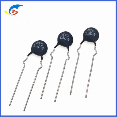
| D-9 NTC Thermistor |
| Part Number MF72 NTC | R25 (Ω) | Max steady-state current(A) | Approximate resistance value at maximum current Ω) | Dissipation coefficient approx. (MW /℃) | Thermal time constant approx. (S) | Operating temperature (°C) | UL |
| 1.5D-9 | 1.5 | 5 | 0.3 | 11 | 36 | -40〜+ 170 | |
| 2.5D-9 | 2.5 | 4.5 | 0.06 | 11 | 36 | -40〜+ 170 | |
| 3D-9 | 3 | 4 | 0.12 | 11 | 35 | -40〜+ 170 | √ |
| 4D-9 | 4 | 3 | 0.19 | 11 | 35 | -40〜+ 170 | √ |
| 5D-9 | 5 | 3 | 0.21 | 11 | 34 | -40〜+ 170 | √ |
| 6D-9 | 6 | 2 | 0.315 | 11 | 34 | -40〜+ 170 | √ |
| 8D-9 | 8 | 2 | 0.4 | 11 | 32 | -40〜+ 170 | √ |
| 10D-9 | 10 | 2 | 0.458 | 11 | 32 | -40〜+ 170 | √ |
| 12D-9 | 12 | 1 | 0.652 | 11 | 32 | -40〜+ 170 | √ |
| 16D-9 | 16 | 1 | 0.802 | 11 | 31 | -40〜+ 170 | √ |
| 20D-9 | 20 | 1 | 0.864 | 11 | 30 | -40〜+ 170 | √ |
| 22D-9 | 22 | 1 | 0.95 | 11 | 30 | -40〜+ 170 | √ |
| 30D-9 | 30 | 1 | 1.022 | 11 | 30 | -40〜+ 170 | √ |
| 33D-9 | 33 | 1 | 1.124 | 11 | 30 | -40〜+ 170 | √ |
| 50D-9 | 50 | 1 | 1.252 | 11 | 30 | -40〜+ 170 | √ |
| 100D-9 | 100 | 0.7 | 1.356 | 11 | 28 | -40〜+ 170 | |
| 200D-9 | 200 | 0.5 | 1.485 | 10 | 28 | -40〜+ 170 | |
| 400D-9 | 400 | 0.2 | 1.652 | 9 | 25 | -40〜+ 170 | |
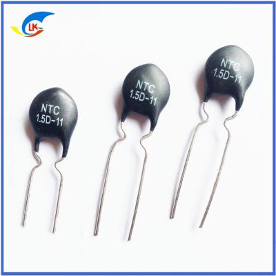
| D-11 NTC Thermistor |
| Part Number MF72 NTC | R25 (Ω) | Max steady-state current(A) | Approximate resistance value at maximum current Ω) | Dissipation coefficient approx. (MW /℃) | Thermal time constant approx. (S) | Operating temperature (°C) | UL |
| 1D-11 | 1 | 5.5 | 0.07 | 13 | 46 | -40〜+ 170 | |
| 1.5D-11 | 1.5 | 5.5 | 0.085 | 13 | 46 | -40〜+ 170 | |
| 2.5D-11 | 2.5 | 5 | 0.095 | 13 | 43 | -40〜+ 170 | √ |
| 3D-11 | 3 | 5 | 0.1 | 13 | 43 | -40〜+ 170 | √ |
| 4D-11 | 4 | 4 | 0.15 | 13 | 44 | -40〜+ 170 | √ |
| 5D-11 | 5 | 4 | 0.156 | 13 | 45 | -40〜+ 170 | √ |
| 6D-11 | 6 | 3 | 0.24 | 13 | 45 | -40〜+ 170 | √ |
| 8D-11 | 8 | 3 | 0.255 | 14 | 47 | -40〜+ 170 | √ |
| 10D-11 | 10 | 3 | 0.275 | 14 | 47 | -40〜+ 170 | √ |
| 12D-11 | 12 | 2 | 0.462 | 14 | 48 | -40〜+ 170 | √ |
| 16D-11 | 16 | 2 | 0.47 | 14 | 50 | -40〜+ 170 | √ |
| 20D-11 | 20 | 2 | 0.512 | 15 | 52 | -40〜+ 170 | √ |
| 22D-11 | 22 | 2 | 0.563 | 15 | 52 | -40〜+ 170 | √ |
| 30D-11 | 30 | 1.5 | 0.667 | 15 | 52 | -40〜+ 170 | √ |
| 33D-11 | 33 | 1.5 | 0.734 | 15 | 52 | -40〜+ 170 | √ |
| 50D-11 | 50 | 1.5 | 1.021 | 15 | 52 | -40〜+ 170 | √ |
| 60D-11 | 60 | 1.5 | 1.215 | 15 | 52 | -40〜+ 170 | √ |
| 80D-11 | 80 | 1.2 | 1.656 | 15 | 52 | -40〜+ 170 | √ |
| D-13 NTC Thermistor |
| Part Number MF72 NTC | R25 (Ω) | Max steady-state current(A) | Approximate resistance value at maximum current Ω) | Dissipation coefficient approx. (MW /℃) | Thermal time constant approx. (S) | Operating temperature (°C) | UL |
| 1.3D-13 | 1.3 | 7 | 0.062 | 13 | 60 | -40〜+ 200 | √ |
| 1.5D-13 | 1.5 | 7 | 0.073 | 13 | 60 | 40〜+ 200 | √ |
| 2.5D-13 | 2.5 | 6 | 0.088 | 13 | 60 | 40〜+ 200 | √ |
| 3D-13 | 3 | 6 | 0.092 | 14 | 60 | 40〜+ 200 | √ |
| 4D-13 | 4 | 5 | 0.12 | 15 | 67 | 40〜+ 200 | √ |
| 5D-13 | 5 | 5 | 0.125 | 15 | 68 | 40〜+ 200 | √ |
| 6D-13 | 6 | 4 | 0.17 | 15 | 65 | 40〜+ 200 | √ |
| 7D-13 | 7 | 4 | 0.188 | 15 | 65 | 40〜+ 200 | √ |
| 8D-13 | 8 | 4 | 0.194 | 15 | 60 | 40〜+ 200 | √ |
| 10D-13 | 10 | 4 | 0.206 | 15 | 65 | 40〜+ 200 | √ |
| 12D-13 | 12 | 3 | 0.316 | 16 | 65 | 40〜+ 200 | √ |
| 15D-13 | 15 | 3 | 0.335 | 16 | 60 | 40〜+ 200 | √ |
| 16D-13 | 16 | 3 | 0.338 | 16 | 60 | 40〜+ 200 | √ |
| 20D-13 | 20 | 3 | 0.372 | 16 | 65 | 40〜+ 200 | √ |
| 30D-13 | 30 | 2.5 | 0.517 | 16 | 65 | 40〜+ 200 | √ |
| 47D-13 | 47 | 2 | 0.81 | 17 | 65 | 40〜+ 200 | √ |
| 120D-13 | 120 | 1.2 | 2.124 | 17 | 65 | 40〜+ 200 | √ |
| D-15 NTC Thermistor |
| Part Number MF72 NTC | R25 (Ω) | Max steady-state current(A) | Approximate resistance value at maximum current Ω) | Dissipation coefficient approx. (MW /℃) | Thermal time constant approx. (S) | Operating temperature (°C) | UL |
| 1.3D-15 | 1.3 | 8 | 0.048 | 18 | 68 | -40〜+ 200 | √ |
| 1.5D-15 | 1.5 | 8 | 0.052 | 18 | 69 | -40〜+ 200 | √ |
| 2.5D-15 | 2.5 | 7 | 0.065 | 18 | 76 | -40〜+ 200 | √ |
| 3D-15 | 3 | 7 | 0.075 | 18 | 76 | -40〜+ 200 | √ |
| 5D-15 | 5 | 6 | 0.112 | 20 | 76 | -40〜+ 200 | √ |
| 6D-15 | 6 | 5 | 0.155 | 20 | 80 | -40〜+ 200 | √ |
| 7D-15 | 7 | 5 | 0.173 | 20 | 80 | -40〜+ 200 | √ |
| 8D-15 | 8 | 5 | 0.178 | 20 | 80 | -40〜+ 200 | √ |
| 10D-15 | 10 | 5 | 0.18 | 20 | 75 | -40〜+ 200 | √ |
| 12D-15 | 12 | 4 | 0.25 | 20 | 75 | -40〜+ 200 | √ |
| 15D-15 | 15 | 4 | 0.268 | 21 | 85 | -40〜+ 200 | √ |
| 16D-15 | 16 | 1 | 0.276 | 21 | 70 | -40〜+ 200 | √ |
| 20D-15 | 20 | 4 | 0.288 | 21 | 86 | -40〜+ 200 | √ |
| 30D-15 | 30 | 3.5 | 0.438 | 21 | 75 | -40〜+ 200 | √ |
| 47D-15 | 47 | 3 | 0.68 | 21 | 86 | -40〜+ 200 | √ |
| 120D-15 | 120 | 1.8 | 1.652 | 22 | 87 | -40〜+ 200 | √ |
| 220D-15 | 220 | 1 | 2.0358 | 24 | 90 | -40〜+ 20 | |
| D-20 NTC Thermistor |
| Part Number MF72 NTC | R25 (Ω) | Max steady-state current(A) | Approximate resistance value at maximum current Ω) | Dissipation coefficient approx. (MW /℃) | Thermal time constant approx. (S) | Operating temperature (°C) | UL |
| 0.7D-20 | 7 | 11 | 0.018 | 27 | 89 | -40〜+ 200 | √ |
| 1D-20 | 1 | 10 | 0.023 | 27 | 89 | -40〜+ 200 | |
| 1.3D-20 | 1.3 | 9 | 0.037 | 27 | 88 | -40〜+ 200 | √ |
| 3D-20 | 3 | 8 | 0.055 | 25 | 88 | -40〜+ 200 | √ |
| 5D-20 | 5 | 7 | 0.087 | 25 | 87 | -40〜+ 200 | √ |
| 6D-20 | 6 | 6 | 0.113 | 25 | 103 | -40〜+ 200 | √ |
| 8D-20 | 8 | 6 | 0.142 | 25 | 105 | -40〜+ 200 | √ |
| 10D-20 | 10 | 6 | 0.162 | 24 | 102 | -40〜+ 200 | √ |
| 12D-20 | 12 | 5 | 0.195 | 24 | 100 | -40〜+ 200 | √ |
| 16D-20 | 16 | 5 | 0.212 | 24 | 100 | -40〜+ 200 | √ |
| 20D-20 | 20 | 4.5 | 0.345 | 23 | 115 | -40〜+ 200 | |
| 30D-20 | 30 | 4 | 0.492 | 23 | 115 | -40〜+ 200 | |
| 47D-20 | 47 | 3.5 | 0.675 | 23 | 120 | -40〜+ 200 | |
| D-25 NTC Thermistor |
| Part Number MF72 NTC | R25 (Ω) | Max steady-state current(A) | Approximate resistance value at maximum current Ω) | Dissipation coefficient approx. (MW /℃) | Thermal time constant approx. (S) | Operating temperature (°C) | UL |
| 0.7D-25 | 0.7 | 12 | 0.014 | 30 | 120 | -40〜+ 200 | |
| 1.5D-25 | 1.5 | 10 | 0.027 | 30 | 121 | -40〜+ 200 | |
| 3D-25 | 3 | 9 | 0.044 | 32 | 124 | -40〜+ 200 | |
| 5D-25 | 5 | 8 | 0.07 | 32 | 125 | -40〜+ 200 | |
| 8D-25 | 8 | 7 | 0.114 | 33 | 125 | -40〜+ 200 | |
| 10D-25 | 10 | 7 | 0.13 | 32 | 127 | -40〜+ 200 | |
| 12D-25 | 12 | 6 | 0.156 | 32 | 126 | -40〜+ 200 | |
| 16D-25 | 16 | 6 | 0.16 | 35 | 126 | -40〜+ 200 | |
| 20D-25 | 20 | 4.5 | 0.184 | 35 | 126 | -40〜+ 200 | |
Note: Multiple resistance values and pin types can be customized on demand.
What is an inrush current suppression power type NTC thermistor
A power NTC thermistor can be a cost-effective device for limiting the amount of inrush current in a switching power supply or other equipment when power is first applied. A power NTC thermistor limits inrush current by acting as a power resistor that drops from a high cold resistance to a low hot resistance when heated by the current flowing through it.
The inrush current limiter supplies the NTC thermistor protection circuit with unnecessarily high current, suppressing high inrush current surges while its resistance remains negligible during continuous operation. Due to its low resistance in the operating state, power thermistors dissipate much less power than fixed resistors commonly used in this application.
Application of Inrush Current Suppression Power Type NTC Thermistor
Limiting inrush current, suitable for protection of switching power supplies, UPS power supplies, transformers, motors, various electric heating appliances, energy-saving lamps, ballasts, various power circuits, amplifiers, color displays, monitors, color TVs, filament protection, etc.
Power thermistor elements can also be used for soft starting of motors, for example, in vacuum cleaners with a continuous current of up to 20 A.
Inrush current suppression power type NTC thermistor advantages:
· Low-cost solid-state device for suppressing inrush current.
· Minimizes line current distortion and radio noise.
· Protects switches, rectifier diodes and smoothing capacitors from premature failure.
· Prevents false fuse blowing.
Inrush current suppression power type NTC thermistor features:
· Resin coated disc thermistor with non-insulated leads.
· Suitable for AC and DC circuits up to 265 V (rms).
· Wide range of resistances, currents and sizes.
· Excellent mechanical strength.
· Suitable for PCB mounting.
Several factors to consider when selecting an inrush current suppression power NTC thermistor
1) Maximum operating current > actual operating current in the power circuit
2) At 25°CRated zero power resistance, E: loop voltage, Im: surge current
For conversion power, recovery power, switching power, UPS power, Im = 100 times the operating current For filaments, heaters, Im = 30 times the operating current
3) The larger the B value, the smaller the residual resistance and the lower the operating temperature.
4) Generally speaking, the larger the time constant and dissipation coefficient, the larger the NTC thermal capacity, and the stronger the surge current suppression capability of the NTC thermistor.
Inrush Current Suppression Power Type NTC Thermistor Application Notes
1) For inrush current limiting, the NTC thermistor must be connected in series with the load circuit. Several inrush current limiters can also be connected in series for higher damping. Inrush current limiters must not be connected in parallel.
2) Generally, inrush current limiters need time to return to a cold state, where they can provide adequate inrush current limiting due to their high resistance. The cooling time depends on the ambient conditions.
3) It should be taken into account that the surrounding area of the NTC thermistor may become hot. Make sure that adjacent components are kept at a sufficient distance from the thermistor to ensure a proper cooling time for the thermistor.
4) Make sure that the design operating temperature of the adjacent materials is comparable to the surface temperature of the thermistor. Make sure that the surrounding components and materials can withstand this temperature.
5) Ensure that the thermistor is adequately ventilated to avoid overheating.
6) Avoid contamination of the thermistor surface.
7) Avoid contact of the NTC thermistor with any liquids and solvents. M
| Because the thermistor is basically customized products, the price of goods is not the original price, the price is subject to the formal quotation. |
| Features | RoHS compliant |
| Halogen-Free (HF) series are available |
| Body size: Ф5mm |
| Radial lead resin coated |
| Operating temperature range: -30℃~+125℃ |
| Wide resistance range |
| Cost effective |
| Recommended Applications | Home appliances;Automotive electronics; Computers;Switch mode power supplies;Adapters |
| Storage Conditions | Storage Temperature: -10℃~+40℃ |
| Relative Humidity: ≦75%RH |
| Keep away from corrosive atmosphere and sunlight. |
| Period of Storage | 1 year |
Product parameters
| P/N | R@25℃ | Tolerance(%) | Beta Value | Tolerance(%) |
| MF11-050 | 5 | ±5 ±10 ±20 | 2400 | ±5 ±10 |
| MF11-100 | 10 | 2800 |
| MF11-150 | 15 | 2800 |
| MF11-200 | 20 | 2800 |
| MF11-220 | 22 | 2800 |
| MF11-270 | 27 | 3000 |
| MF11-330 | 33 | 3000 |
| MF11-390 | 39 | 3000 |
| MF11-470 | 47 | 3100 |
| MF11-500 | 50 | 3100 |
| MF11-680 | 68 | 3100 |
| MF11-820 | 82 | 3100 |
| MF11-101 | 100 | 3200 |
| MF11-121 | 120 | 3200 |
| MF11-151 | 150 | 3200 |
| MF11-201 | 200 | 3200 |
| MF11-221 | 220 | 3500 |
| MF11-271 | 270 | 3500 |
| MF11-331 | 330 | 3500 |
| MF11-391 | 390 | 3500 |
| MF11-471 | 470 | 3500 |
| MF11-501 | 500 | 3500 |
| MF11-561 | 560 | 3500 |
| MF11-681 | 680 | 3800 |
| MF11-821 | 820 | 3800 |
| MF11-102 | 1000 | 3800 |
| MF11-122 | 1200 | 3800 |
| MF11-152 | 1500 | 3800 |
| MF11-202 | 2000 | 4000 |
| MF11-222 | 2200 | 4000 |
| MF11-272 | 2700 | 4000 |
| MF11-302 | 3000 | 4000 |
| MF11-332 | 3300 | 4000 |
| MF11-392 | 3900 | 4000 |
| MF11-472 | 4700 | 4050 |
| MF11-502 | 5000 | 4050 |
| MF11-562 | 5600 | 4050 |
| MF11-682 | 6800 | 4050 |
| MF11-822 | 8200 | 4050 |
| MF11-103 | 10000 | 4050 |
| MF11-123 | 12000 | 4050 |
| MF11-153 | 15000 | 4150 |
| MF11-203 | 20000 | 4300 |
| MF11-303 | 30000 | 4300 |
| MF11-473 | 47000 | 4300 |
| MF11-503 | 50000 | 4300 |
| MF11-683 | 68000 | 4300 |
| MF11-104 | 100000 | 4500 |
| MF11-124 | 120000 | 4700 |
| MF11-154 | 150000 | 4700 |
| MF11-204 | 200000 | 4700 |
| MF11-304 | 300000 | 4700 |
| MF11-504 | 500000 | 4800 |
| MF11-105 | 1000000 | 4900 |
Negative temperature coefficient thermistor, also known as NTC thermistor, is a kind of sensor resistance whose resistance value decreases with the increase of temperature. Widely used in various electronic components, such as temperature sensors, resettable fuses and self-adjusting heaters, etc.
The matters needing attention in the use of NTC are as follows
1. Be sure to add a suitable series resistor, otherwise the thermal collapse will occur when the NTC is in use, because the current flowing through the NTC will generate heat, if the heat cannot be dissipated in time, the temperature of the NTC will rise, and then the resistance will drop, at this time The current will increase significantly, and the NTC will get hotter, so that cycling can eventually cause the NTC to burn out, or even catch fire.
2. The end electrode of NTC is usually composed of Ag, and silver migration will occur when it is used improperly, resulting in short circuit of NTC. Avoid NTC contact with water during use.
3. The high temperature during welding will cause the irreversible resistance drift of NTC. In some cases, it may cause a 5% drift, so try to avoid high temperature welding.