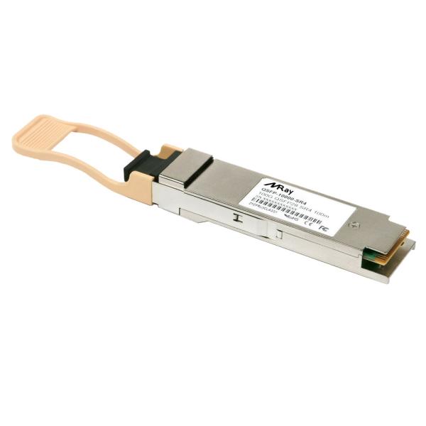
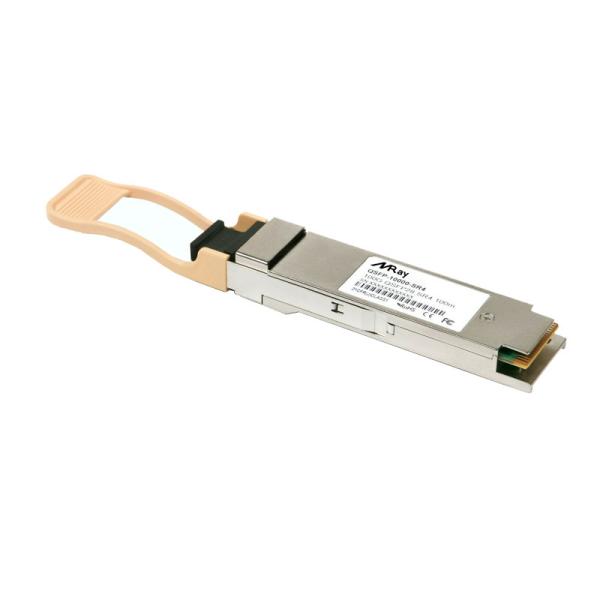
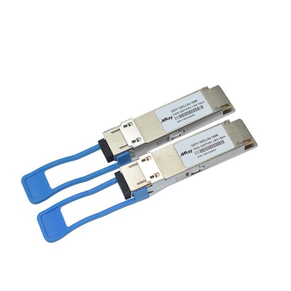
The 100GBASE-LR4 QSFP28 transceiver converts 4 input channels of 25 Gbps electrical data to 4 channels of LAN WDM optical signals and then multiplexes them into a single channel for 100G optical transmission. It focuses on longer transmission distance over single-mode fiber.
On the receiver side, the module demultiplexes a 100G optical input into 4 channels of LAN WDM optical signals and then converts them to 4 output channels of electrical data. 100G QSFP28 LR4 has a duplex LC interface, The central wavelengths of the 4 LAN WDM channels are 1295.56, 1300.05, 1304.58 and 1309.14 nm as members of the LAN WDM wavelength grid defined in IEEE 802.3ba. The 100GBASE-LR4 QSFP28 transceiver provides superior performance for 100G applications up to 10 km over SMF and compliant to optical interface with IEEE802.3ba 100GBASE-LR4 requirements.
QSFP28 LR4 100G transceiver module is designed for 100Gigabit Ethernet links over 10Km single mode fiber. It is compliant with IEEE 802.3ba 100GBASE-LR4. Digital diagnostics functions are available via an I2C interface, as specified by the QSFP28 MSA.
Parameter | Symbol | Unit | Min | Typ | Max |
Operating Case Temperature Range | Tc | oC | 0 |
| 70 |
Power Supply Voltage | Vcc | V | 3.14 | 3.3 | 3.46 |
Bit Rate | BR | Gb/s |
|
| 103.1 |
Bit Error Ratio | BER |
|
|
| 10-12 |
Max Supported Link Length | L | Km |
|
| 10 |
Parameter | Symbol | Unit | Min | Typ | Max | Notes |
Transmitter(per Lane) | ||||||
Signaling Speed per Lane |
| GBd | 25.78125 ± 100 ppm |
| ||
Lane Wavelength (range): L0 L1 L2 L3 |
| nm | 1294.53 – 1296.59 1299.02 – 1301.09 1303.54 – 1305.63 1308.09–1310.19 |
| ||
Total Average Launch Power | Pout | dBm |
|
| 10.5 |
|
Transmit OMA per Lane | TxOMA | dBm | -1.3 |
| 4.5 |
|
Average Launch Power per Lane | TXPx | dBm | -4.3 |
| 4.5 |
|
Optical Extinction Ratio | ER | dB | 4 |
|
|
|
Side-Mode Suppression Ratio (SMSR) | SMSR | dB | 30 |
|
|
|
Average launch power of OFF transmitter, per lane |
| dBm |
|
| -30 |
|
Relative Intensity Noise | RIN | dB/Hz |
|
| -128 |
|
Optical Return Loss Tolerance |
| dB |
|
| 20 |
|
Transmitter Reflectance |
| dB |
|
| -12 |
|
Transmitter Eye mask definition {X1,X2,X3, Y1,Y2,Y3} |
|
| {0.25,0.4,0.45,0.25,0.28,0.4} |
| ||
Receiver(per Lane) | ||||||
Signaling Speed per Lane |
| GBd | 25.78125 ± 100 ppm |
| ||
Lane Wavelength (range): L0 L1 L2 L3 |
| nm | 1294.53 – 1296.59 1299.02 – 1301.09 1303.54 – 1305.63 1308.09–1310.19 |
| ||
Receiver Sensitivity (OMA) per Lane | Rxsens | dBm |
|
| -8.6 | dBm |
Average Received Power per Lane | RXPx | dBm | -10.6 |
| 4.5 |
|
Damage Threshold Per Lane | Pmax | dBm |
|
| 3.4 |
|
Return Loss | RL |
|
|
| -26 |
|
Vertical eye closure penalty, per lane |
| dB |
|
| 1.9 |
|
Receiver electrical 3dB upper cutoff frequency,per lane |
| GHz |
|
| 31 |
|
LOS De-Assert | LOSD | dBm |
|
| -11.6 |
|
LOS Assert | LOSA | dBm | -24 |
|
|
|
LOS Hysteresis |
| dB |
| 1.5 |
|