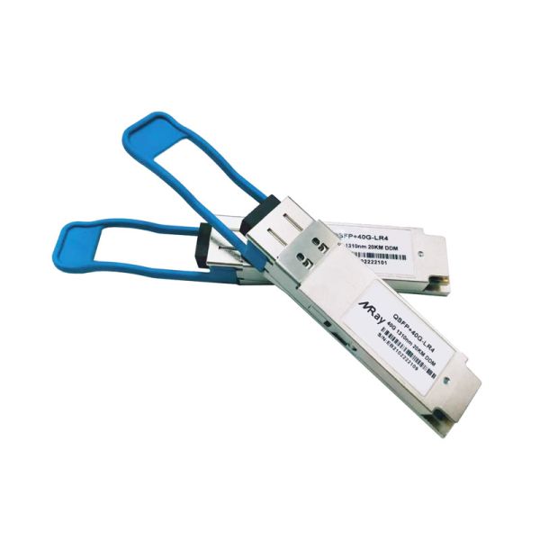
The QSFP-4010-LR4 is a 40G LR4 single-mode multi-rate QSFP+ transceiver using 4 CWDM wavelengths running 1271 ~ 1331nm and reaching up to 10Km distance on single-mode 9/125um fiber. Each CWDM channel runs 10G and they are aggregated on a built-in mux/demux inside the QSFP module. The module can be used for 40G Ethernet, SONET or SDH networks.
The LR4 standard is used for medium range fiber connections over 9/125um single-mode fiber. The optical connectors are LC on the QSFP-4010-LR4. The widespread LC connector provides easy connectivity with common fiber cabling, making the transceiver a convenient choice.
Miray transceivers have been tested for compatibility with a large variety of networking devices from well known brands like: Cisco, Juniper, Force10, Edge-Core, ZyXEL, D-Link and many others. The transceivers follow the industry standards of QSFP Multi-Source Agreement (MSA), making them directly interchangeable with any networking device following industry standards.
Parameter | Symbol | Unit | Min | Typ | Max |
Operating Case Temperature Range | Tc | oC | 0 |
| 70 |
Power Supply Voltage | Vcc | V | 3.14 | 3.3 | 3.46 |
Bit Rate | BR | Gb/s |
|
| 41.2 |
Bit Error Ratio | BER |
|
|
| 10-12 |
Max Supported Link Length | L | Km |
|
| 10 |
Parameter | Symbol | Min | Typical | Max | Unit | |
Center Wavelength | Ch0 | λ0 | 1264.5 | - | 1277.5 | nm |
Ch1 | λ1 | 1284.5 | - | 1297.5 | nm | |
Ch2 | λ2 | 1304.5 | - | 1317.5 | nm | |
Ch3 | λ3 | 1324.5 |
| 1337.5 | nm | |
Bit Rate per Channel | B | 10.3125 |
| 10.7546 | Gb/s | |
Total Average Launch Power | POUT | - | - | 8.0 | dBm | |
Side Mode Suppression Ratio | SMSR | 30 | - | - | dB | |
Average launch power, each lane |
| -6.8 | - | 2.0 | dBm | |
Optical Modulation Amplitude (each lane) | OMA | -3.8 | - | 3.5 | dBm | |
Optical Modulation Amplitude (OMA) - TDP, per lane (min) | - | -4.8 | - | - | dBm | |
Transmission & dispersion penalty, each lane | TDP | - | - | 2.3 | dB | |
RIN12 OMA | - | - | - | -128 | dB/Hz | |
Transmitter Reflectance | - | - | - | -12 | dB | |
Extinction Ratio | ER | 3.5 | - |
| dB | |
Transmitter eye mask definition {X1, X2, X3, Y1, Y2, Y3} |
{0.25, 0.4, 0.45, 0.25, 0.28, 0.4} | |||||
Average launch power of OFF transmitter, each lane | - | - | - | -30 | dBm | |
Optical return loss tolerance | - | - | - | 20 | dB |
Parameter | Symbol | Min | Typical | Max | Unit | |
Center Wavelength | Ch0 | λ0 | 1264.5 | 1271 | 1277.5 | nm |
Ch1 | λ1 | 1284.5 | 1291 | 1297.5 | nm | |
Ch2 | λ2 | 1304.5 | 1311 | 1317.5 | nm | |
Ch3 | λ3 | 1324.5 | 1331 | 1337.5
| nm | |
Bit Rate per Channel | B | 10.3125 | - | 10.7546 | Gb/s | |
Damage threshold, each lane | - | 3.4 | - | - | dBm | |
Average receive power, each lane | - | -13.5 | - | 2.0 | dbm | |
Unstressed Sensitivity (OMA) at 10 x 10-12BER | OMAin | - | - | -11.5 | dBm | |
Stressed Sensitivity (OMA) | OMAin,str | - | - | -9.9 | dBm | |
Receiver Reflectance | ORL | - | - | -26 | dB | |
Vertical eye closure penalty, each lane | VECP | - | - | 1.6 | dB | |
Receive electrical 3 dB upper cutoff frequency, per lane | - | - | - | 12.3 |
GHZ | |
Stressed eye J2 Jitter, each lane | J2 | - | - | 0.42 | UI | |
Stressed eye J9 Jitter, each lane | J9 | - | - | 0.65 | UI | |
Eye mask coordinates #1 {X1, X2 Y1, Y2} Hit ratio = 5 x 10E-5 |
{ 0.29, 0.5 150, 425} |