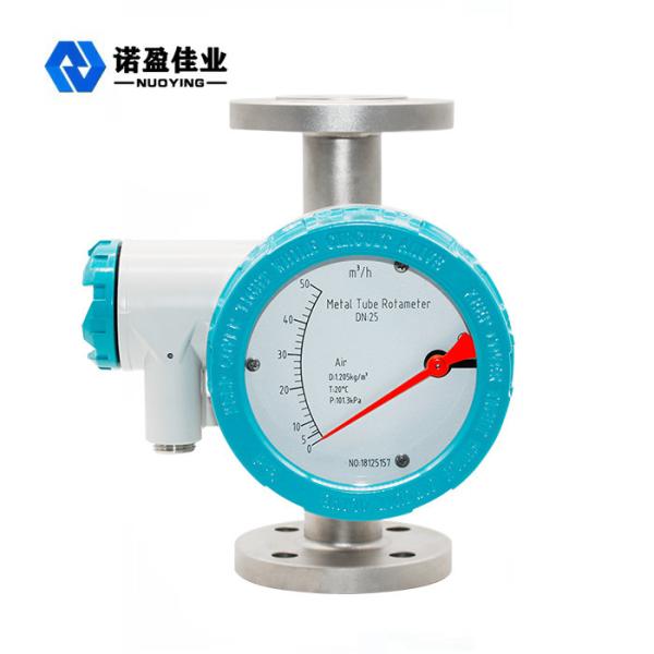
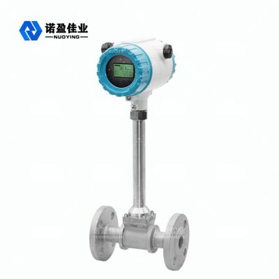
NYLD-LGQ Gas Roots Flowmeter
The NYLD-LGQ gas roots flowmeter has been used as a volumetric meter for more than 100 years. With the features such as high precision, wide range, small volume, light weight, convenient installation and maintenance, reliable and durable service life, it is widely used in natural gas, coal gas, air and other gas flowmeters.It is an ideal flowmeter device for urban gas, oilfield chemical, scientific research and other departments at home and abroad.
NYLD-LGQ Gas Roots Flowmeter Technical Parameters
Model specification | Nominal diameterDN mm) |
Flow limit (m3/h) |
Starting flow m3/h |
Pressure loss at Qmax |
Nominal pressure MPa |
Accuracy % |
Range |
Material |
NYLD-LGQ-20A | 25 | 20 | 0.05 | 100 | 1.0 1.6 | 1.0 1.5 | 20:1 | Aluminum allo |
NYLD-LGQ-40A | 40 | 30 | 0.07 | 100 | 30:1 | |||
NYLD-LGQ-40B | 40 | 40 | 0.07 | 140 | 40:1 | |||
NYLD-LGQ-50A | 50 | 60 | 0.1 | 100 | 65:1 | |||
NYLD-LGQ-50B | 50 | 80 | 0.1 | 140 | 70:1 | |||
NYLD-LGQ-80A | 80 | 100 | 0.1 | 110 | 70:1 | |||
NYLD-LGQ-80B | 80 | 150 | 0.12 | 150 | 120:1 | |||
NYLD-LGQ-80C | 80 | 200 | 0.15 | 180 | 70:1 | |||
NYLD-LGQ-100A | 100 | 250 | 0.11 | 180 | 80:1 | |||
NYLD-LGQ-100B | 100 | 300 | 0.11 | 130 | 110:1 | |||
NYLD-LGQ-100C | 100 | 450 | 0.1 | 200 | 110:1 | |||
NYLD-LGQ-150A | 150 | 650 | 0.65 | 350 | 80:1 | Aluminum | ||
NYLD-LGQ-150B | 150 | 1000 | 0.76 | 450 | 90:1 | |||
NYLD-LGQ-200A | 200 | 1600 | 1.15 | 500 | 53:1 |
NYLD-LGQ Gas Roots Flowmeter Operating Principle
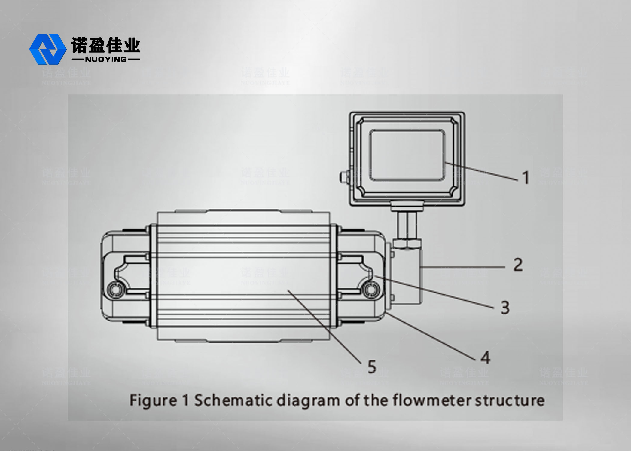
(1).The flowmeter consists of 5 parts (see Figure 1)
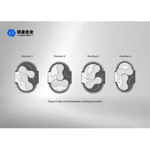
(2).Intelligent gas roots flowmeter working principle (see Figure 2)
The intelligent gas roots flowmeter consists of a housing, a conjugate rotor and an intelligent flow totalizer. Under the action of the pressure difference between the inlet and outlet of the circulating gas (P inlet>P>outlet),the pair of conjugate maintain the correct relative position of the rotor through the precision-machined adjusting gear.The optimum working gap between the rotor, the rotor and the housing, and the rotor and the wall plate achieves a continuous non-contact seal.
For each revolution of the rotor,it outputs four times theeffective volume of the metering chamber, and the number of revolutions of the rotor is transmitted to the intelligent flow totalizer through the magnetic sealing coupling device and the speed reducing mechanism, to display the cumulative volume of the output gas. (The figure shows only a quarter cycle).
(3).Intelligent flow totalizer working principle
The intelligent flow totalizer consists of temperature and pressure detection analog channel, flow sensor channel and microprocessor unit, and is equipped with an external signal interface to output various signals. The microprocessor in the intelligent flow totalizer performs temperature and pressure compensation and compression factor correction according to the gas equation. The gas equation is as follows:
Where:
Qn: volume flow rate under standard condition (m3/h);
Qg: volume flow rate under working condition (m3/h);
Pg: meter pressure at the flowmeter pressure detection point (KPa)
Pa: local atmospheric pressure (KPa);
Tg: absolute temperature(273.15 + t) (K) of the medium;
t: measured medium temperature (°C);
Zn: compression factor under standard condition;
Zg: compression factor under working condition;
Tn: absolute temperature (273.15+20) (K) under standard state;
Pa: local atmospheric pressure (KPa);
Pn: standard atmospheric pressure (101.325KPa);
P: P = Pa + Pg.
Note:For natural gas Zn/Zg=Fz2, Fz is called super compression factor. This product is calculated according to the formula of SY/T6143-1996 of CNPC standard.