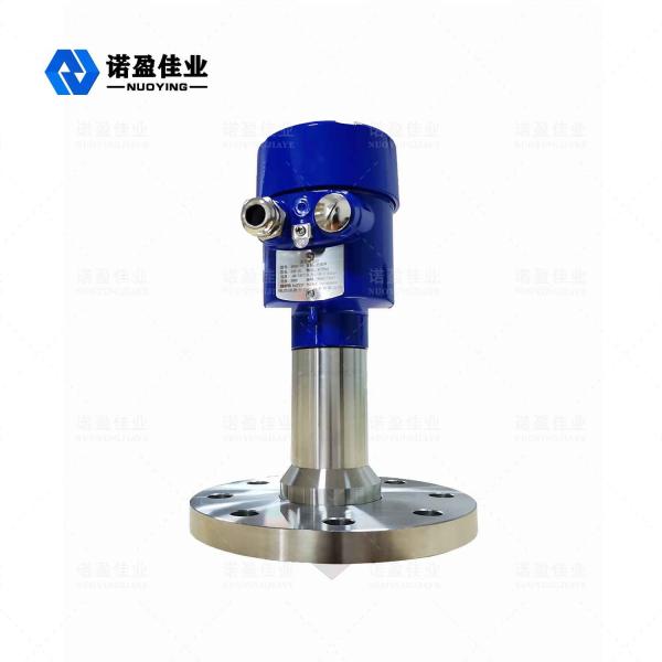
NYRD705 1.8GHz Guided Wave Radar Level Meter
Guided wave radar level gauge, a level measuring instrument in chemical industry. Guided wave radar level meter is a radar level meter based on the principle of time domain reflectometry (TDR). The electromagnetic pulse of the radar level meter travels along the cable or probe rod at the speed of light. When it meets the surface of the measured medium, part of the pulse of the radar level meter is reflected to form an echo and returns to the pulse transmitter along the same path. The distance between the launcher and the surface of the measured medium is proportional to the propagation time of the pulse in the meantime, and the height of the liquid level is calculated.
Radar Level Meter Technical Parameter
Typical application | Liquids, powders, solid particles, corrosive media |
Antenna material | Flexible cable/304/PTFE (optional) |
Measuring range | 6 m |
Accuracy | ±1mm |
Power supply | 24 VDC(Two-wire,Four- wire) |
Medium temperature | -40~+130℃,-40~+250℃ |
Pressure | -0.1~4.0MPa |
Process connection | Thread, Flange (optional) |
Protection class | IP67 |
Explosion-proof grade | ExiaⅡCT6(optional) |
Signal output | 4...20mA/HART/RS485/Modbus... |
※ Note: Products can be customized according to the specific requirements of users!
Radar Level Meter Operating Principle
The high-frequency microwave pulse emitted by the guided wave radar propagates along the detection component (steel cable or steel rod), and when it encounters the measured medium, due to the sudden change of the dielectric constant, it causes reflection, and a part of the pulse energy is reflected back. The time interval between the transmitted pulse and the reflected pulse is proportional to the distance of the measured medium.
Radar Level Meter Installation requirements
Standard installation method
◎ It is recommended to install at 1/4 or 1/6 of the container diameter.
Note: The minimum distance from the tank wall is L0≥300mm, H0≥50mm.
◎ Keep away from the inlet and outlet.
◎ Keep clear of obstacles such as limit switches, heating coils, agitators, etc. Note: The distance between the probe and the obstacle is ≥200mm.
◎ When the container is a metal can, the radar should not touch the wall and bottom of the can in the whole range.
◎ If the bottom of the container is tapered, the radar can be installed in the center of the top of the tank.
◎ The height of the installation short pipe should be L1≤10cm.
Radar Level Meter Electricalconnections
◎ Supply voltage
(4 ~20)mA/HART(Two-wire)
The power supply and the output current signal share a two-core shielded cable. Refer to the technical data for the specific supply voltage range. For the intrinsically safe type, a safety barrier must be added between the power supply and the instrument.
(4~20)mA/HART(Four-wire)
The power supply and the current signal are separated, and each uses a two-core shielded wire. Refer to the technical data for the specific supply voltage range.
RS485/Modbus
The power supply and the Modbus signal are separated, and each uses a two-core shielded wire. For specific supply voltage range see technical data .
◎ Connection method
◎ Explosion-proofconnection
Radar Level Meter SelectionTabel
For example: NYRD705-AC1A33VAPM1000
Manufacturer number | |
NYRD | |
Product model | |
705 Range 6m | |
Antenna form/ Size/ Material | |
A B Y | Cable antenna/ 304 Cable antenna/ PTFE Special Customized |
Process connection | |
A | Thread: G1½A |
B | Thread: G1A |
C | Thread: G¾A |
D | Thread: 1½NPT |
E | F l a n g e : DN50 |
F | Flange: DN80 |
G | Flange: DN100 |
Y | Special customized |
Output/Supply | |
1 4~20mA/24VDC Two-wire 2 4~20mA/24VDC/Hart Two-wire 3 4~20mA/220VAC/Hart Four-wire 4 RS485/Modbus | |
Live display/ Programming | |
A X | With Without |
Nuoying code | |
XX |
Process temperature |
1 - 40~+ 130℃ |
2 - 40~+ 250℃ |
3 - 40~+ 500℃ |
Y Special customized |
Process pressure |
1 - 0.1~+ 0.3MPa |
2 - 0.1~+ 2.0MPa |
3 - 0.1~+ 4.0MPa |
Y Special customized |
Sealing |
V Viton K Kalrez Y Special customized |
Housing material/ protection level |
A Aluminum/ IP65 |
D Aluminum ( Dual Cavity)/ IP67 |
S SS 304/ IP68 |
Y Special customized |
Explosion-proof grade |
P Standard |
L Exia IICT6 |
G Exd[ia] IICT6 Special |
Y customized |
Cable entry |
M M20×1. 5 N 1/ 2" NPT Y Special customized |
Range ( unit: cm) |
X ...... |