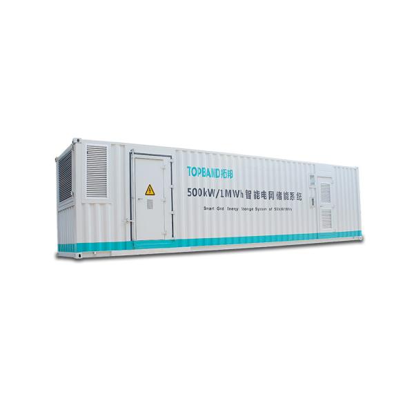
400AH Home Battery Storage Systems , Battery Electric Storage System Canbus Communication
1. General Information
This specification defines the performance of rechargeable LiFePO4 battery pack TB48400F-T110B manufactured by Shenzhen Topband Battery Co., Ltd, describes the type, performance, technical characteristics, warning and caution of the battery pack.
2. Specification
NO | Items | Description | |
Normal Specification | |||
1 | Nominal Voltage | 51.2V | |
2 | Normal Capacity | 400Ah | |
3 | Internal Resistance | ≤20mΩ | |
4 | Battery system info. Display and communication | Support LCD display and RS485 communication, to display battery voltage, current, temp., SOC, etc. | |
Standard Charge | |||
5 | Battery operation temperature range @charging | 0~45℃ | |
6 | Normal charge voltage | 58.4±0.1V | |
7 | Recommended float charge voltage(for Standby use) | 55.6±0.1V | |
8 | Allowed MAX charge current | 100A@ Battery initial Temp 25±5℃ | |
9 | Recommended charge current | ≤60A | |
Standard Discharge | |||
10 | Battery operation temperature range @discharging | -20~60℃ | |
11 | Output voltage range | 40~58.4V | |
12 | Allowed discharge current | 300A withstand 10min @Battery initial Temp 25±5℃ | |
13 | Pulse discharge current | 350A/20s | |
14 | Discharge cut-off voltage | 40V | |
Mechanical Characteristics | |||
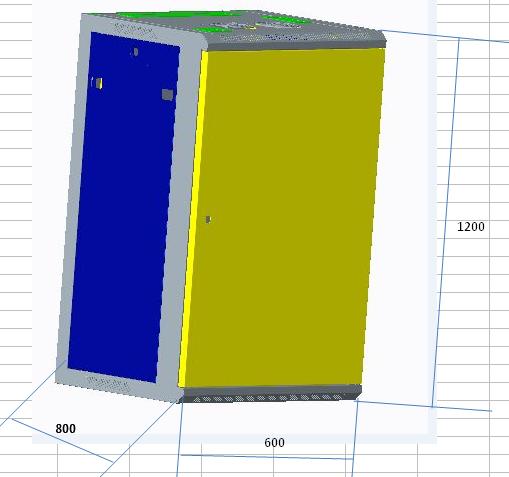
15 | Dimension | Depth 800mm±3m | |
Width 600mm±3m | |||
Height 1200mm±3m | |||
16 | Dimension of battery box | 498*590*175.5mm | |
17 | Dimension of controller box | 482*422*177mm | |
18 | Total Weight | 333Kg±2kg | |
Storage | |||
19 | Storage Temperature & Humidity Range | Short: within one month | -20~35℃, 45~75%RH |
Long: above one month | -10~30℃, 45~75%RH | ||
20 | Self-discharge rate | Residual capacity | ≤3% per month; ≤15% per year |
Reversible capacity | ≤1.5%per month; ≤8% per year |
3. Electrical Characteristics & Test Condition.
@Ambient Temperature 25±5℃ & Humidity 45%~75%.
NO | Items | Criterion | Condition | |
1 | Internal Impedance | ≤20mΩ | Test the internal resistance of 50% SOC battery pack with 1 kHz AC internal resistance test instrument. | |
2 | Nominal Capacity | ≥380Ah | Rest for 1 hour after fully charged, then discharge with 0.33C current until the battery reaches the discharge cutoff voltage. | |
3 | Short circuit protection | / | Not allowed. | |
4 | MAX charge Current | 100A | Charging with this current for more than 0.5h and the added temperature of battery pack less than 20℃. | |
5 | MAX discharge Current | 150A | Discharging with this current for more than 10min and the added temperature of battery pack less than 35℃. | |
6 |
Cycle life (DOD%100) | ≥2000 cycles | Discharge with the current of 0.5C until it can’t discharge, and then rest it for 1h. Charge the battery following CC(0.33C)/CV mode to full capacity, and then rest it for 1h. Repeat above process until full charged capacity is no more than 80% of normal value. Accumulated times is defined as cycle life. | |
7 |
Discharge Temperature Characteristics | -20℃ | ≥70% | At 25±5℃ discharge the battery with the current of 0.33C to the cut-off voltage and record charge capacity. Store the battery at various temperatures for 2h and discharge the battery with 0.33C to the cut-off voltage. |
0℃ | ≥80% | |||
25℃ | 100% | |||
55℃ | ≥95% | |||
8 |
Charge Retention ability |
remain capacity≥90% | Charge the battery to full capacity and store it for 28days, and then discharge it with 0.33C to the cut-off voltage. |
4. Circuit Protection
The batteries are supplied with a LiFePO4 Battery Management System (BMS)that can monitor and optimized each single prismatic cell during charge & discharge, to protect the battery pack overcharge, over discharge, over current, over heat, etc. It would cut off the battery input or output for protection once necessary. Overall, the BMS helps to ensure safe and accurate running.
Test item | Content | Criterion |
Over charge | Over-charge protection for each cell | 3.80±0.03V |
Over-charge release for each cell | 3.60±0.05V | |
Over-charge release method | Under the release voltage | |
Over discharge | Over-discharge protection for each cell | 2.50±0.05V |
Over-discharge release for each cell | 2.80±0.05V | |
Over-discharge release method | Release after charge | |
Over current | Discharge over current protection | 200~300A |
Protection delay time | 20~40s | |
Over current release method | Release after cutoff the load. | |
Battery temperature | Battery Over temperature | Protection @65±5℃ |
Release @55±5℃ | ||
Over-charge protection for each cell | Protection @-20±5℃ | |
Release @-10±5℃ |
5. Dimensional Drawing
6. Installation
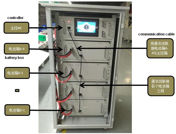
a,install the 4 battery boxes and controller box into cabinet in order;
b,connect the battery boxes and controller box with communication cables;
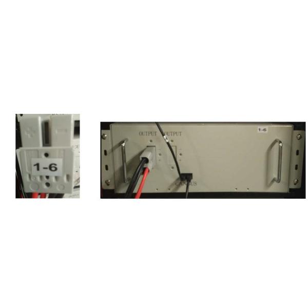
c,connect the battery boxes and controller box with power cables( the code of Anderson connectors are one-to-one correspondence)
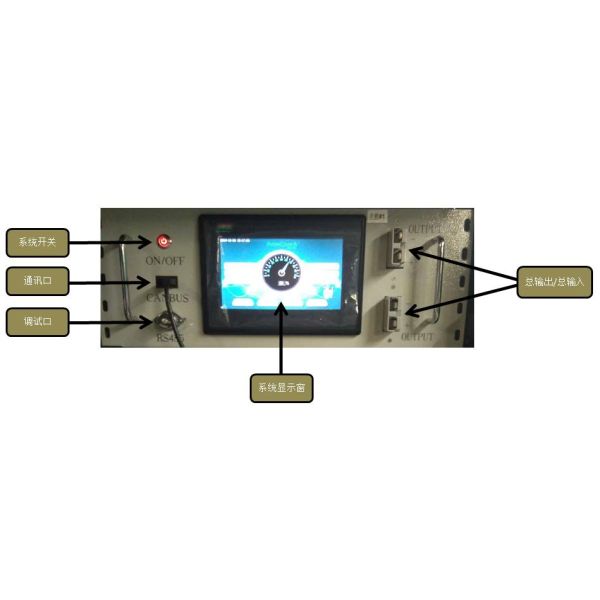
7. Controller display panel