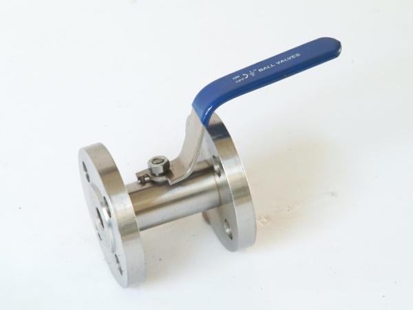
Full Bore And Reduced Bore Floating Ball Valve Ductile Iron / Stainless Steel Body
Floating Ball Valve Introduction
1) Ball Valve (1" ) DN25,2pc-Flanged /Hose Ball Valve ,Blowout Proof Stem, Anti-Static Design ,PN16,EN1092-1,RF,Working Temperatures (-29C to +427C)
2) Ball Valve ( 1 1/4" ) DN25,2pc-Flanged /Hose Ball Valve, Blowout Proof Stem, Anti-Static Design ,PN16,EN1092-1,RF,Working Temperatures (-29C to +427C)
3) Ball Valve (3/4" ) DN25,2pc-Flanged /Hose Ball Valve, Blowout Proof Stem, Anti-Static Design ,PN16,EN1092-1,RF,Working Temperatures (-29C to +427C)
BALL VALVE:
W.N.R.F. Flanged Ball Valves, Full bore, lever operated, ANSI Class 150/300. Dimensions
API 6D and, tests to API with following parameters:
Body Material : ASTM A216 WCB
Ball and Trim Material : Stainless Steel
Lever Material : Forged steel with Zn coated
Seat Material : PTFE
Working Temperature : 05°C to 50°C
Working Pressure : 150 Psig./350 Psig.
Fluid to be handled : Natural Gas
(Odorized) containing 0.5% CO2 by volume.
Description:
The ball valve is designed and manufactured according well to API 608. Floating ball when small caliber,
and fixed ball when large caliber.
It has fire protection structure and antistatic device. Widely used for petroleum, chemistry, water
treatment industries.
Floating Ball Valve Features:
- Anti-blowout Structure of Valve Stem
When medium pass through the valve, the pressure in valve body may possibly push the stem out, or
when the valve is in repair, if there is pressure in the middle cavity, the stem or medium seems to easily
fly out upon disassembling the valve, which can cause injures to human beings, To prevent the
possibilities, a dummy club is packing and thrust bearing are burnt or packing is damaged due to other
causes, the pressure of medium in valve body will make the dummy club of valve stem in close contact
with the upper seal face of valve body. Thus to prevent medium leaking out from the damage packing
position.
-Prompt switch
The ball valve circumrotates in 90°,It work quickly to open or close.
Test Pressure
Main Connection Dimensions
|
Type | Size(mm) | Dimension(mm) | ||||||||
| inch | DN | L | D | D1 | D2 | b | Z-Φd | H | W |
Q41F/H/Y-300Lb | 1/2″ | 15 | 140 | 95 | 66.5 | 35 | 15 | 4-Φ15 | 72 | 115 |
| 3/4″ | 20 | 152 | 117 | 82.5 | 43 | 16 | 4-Φ19 | 75 | 130 |
| 1″ | 25 | 165 | 124 | 89 | 51 | 18 | 4-Φ19 | 85 | 150 |
| 11/4″ | 32 | 178 | 133 | 98.5 | 64 | 19.5 | 4-Φ19 | 95 | 180 |
| 11/2″ | 40 | 190 | 156 | 114.3 | 73.2 | 21 | 4-Φ22 | 110 | 230 |
| 2″ | 50 | 216 | 165 | 127 | 92 | 23 | 8-Φ19 | 120 | 240 |
| 21/2″ | 65 | 241 | 190.5 | 149.4 | 104.7 | 26 | 8-Φ22 | 150 | 280 |
| 3″ | 80 | 283 | 210 | 168.5 | 127 | 29 | 8-Φ22 | 165 | 310 |
| 4″ | 100 | 305 | 254 | 200.2 | 157 | 32 | 8-Φ22 | 190 | 330 |
| 5″ | 125 | 381 | 279 | 235 | 185.7 | 35 | 8-Φ22 | 240 | 600 |
| 6″ | 150 | 403 | 318 | 270 | 216 | 37 | 12-Φ22 | 270 | 800 |
| 8″ | 200 | 502 | 381 | 330 | 270 | 42 | 12-Φ25 | 315 | 1000 |
| 10″ | 250 | 568 | 445 | 387.5 | 324 | 48 | 16-Φ29 | 380 | 1200 |
Type | Size(mm) | Dimension(mm) | ||||||||
| inch | DN | L | D | D1 | D2 | b | Z-Φd | H | W |
Q41F/H/Y-600Lb | 1/2″ | 15 | 165 | 95 | 66.5 | 35 | 15 | 4-Φ15 | 88 | 115 |
| 3/4″ | 20 | 190 | 118 | 82.5 | 43 | 16 | 4-Φ19 | 98 | 130 |
| 1″ | 25 | 216 | 124 | 89 | 51 | 18 | 4-Φ19 | 105 | 150 |
| 11/2″ | 40 | 241 | 156 | 114.3 | 73.2 | 23 | 4-Φ22 | 135 | 180 |
| 2″ | 50 | 292 | 165 | 127 | 92 | 26 | 8-Φ19 | 155 | 240 |
| 3″ | 80 | 356 | 210 | 168.2 | 127 | 32 | 8-Φ22 | 175 | 280 |
| 4″ | 100 | 432 | 273 | 216 | 157 | 38 | 8-Φ25 | 210 | 330 |
| 6″ | 150 | 559 | 356 | 292 | 216 | 48 | 12-Φ29 | 340 | 800 |
| 8″ | 200 | 660 | 419 | 349 | 270 | 56 | 12-Φ32 | 400 | 1000 |
| 10″ | 250 | 787 | 508 | 432 | 324 | 64 | 16-Φ35 | 440 | 1200 |