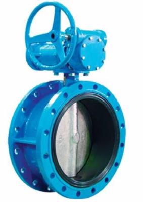
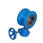
Automatic Double Flanged Butterfly Valves Flanged Resilient Sealing DN2000
Double Flanged Butterfly Valves Specification
Seat Ring: EPDM food graded;
Shaft:SS420;
Gear Box with Hand Wheel;
FBE color:RALBlue5005/5002/5017
Double Flanged Butterfly Valves Standard
Flange Drilling in acc. to EN 1092-2;
Worm Gear Box with Hand Wheel;
ISO 5211 Mounting Flange standard;
Testing in acc. EN 12266-1;
Fusion Bonded Non-toxic Epoxy Powder Coating w/o NSF61/WRAS
Double Flanged Butterfly Valves introduction:
Double eccentric end flanged resilient sealing butterfly valve is operated by the disc rotating form
0° to 90°, can be applied to cut off or regulate the flow of medium
The valve can be actuated by operating lever, handle wheel, electric actuator or pneumatic actuator.
Widely used for potable water supply and distribution, electric power plant, gas supply, warm-air system,
smelting plant, chemical industry.
(DN250 10inch butterfly valve)
face to face length: 10 inch valve length be 8inch(203mm).
Body Ductile Iron w/Fusion Bonded Epoxy ASTM A536 65-45-12
Disc Ductile Iron w/316SS Edge w/Fusion Bonded Epoxy ASTM A536 65-45-12
Seat NBR Vulcanized on Body (Buna-N)
Shaft Type 316 Stn. Stl ASTM A276 Ty316
Packing V-Ring NBR (Buna-N)
Flanges ANSI B 16.1 Class 125
Specifications:
Size: DN50 - 3000
Temperature: -15℃ - 150℃
Pressure: 1.0MPa/1.6MPa
High Temperature Butterfly Valves Features:
⊙ Professional design
When initiating the rotary opening movement the disc is off-seated after only a few
degree of opening movement and there is very little wear and tear between seat ring and disc.
⊙ Combine fastness
Stainless steel seat ring is rolled into the valve body by applying special rolling technology
when DN<1200. Ultrasonic spray applies seal of valve body when DN>1400.
⊙ Excellent corrosion protection
Inside electrostatic epoxy resin power coating or vitreous enamel(upon request), outside electrostatic
epoxy resin power coating.
⊙ Reliable health nature
Epoxy resin power is up to the health standard.
Mail part & material
Body, Disc: GGG50 with internal and external epoxy resin coating
Stems: 1Cr17Ni12Mo2Ti, Stainless steel min.13%Cr
Bushing :Bronze CuAI10Fe3
Seal ring, O-ring: NBR, EPDM or FPM
Technical Specification
- Nominal diameter:150~2600mm
- Nominal pressure:1.0/1.6/2.5Mpa
- Strength testing pressure:1.5/2.4/3.75Mpa
- Sealing testing pressure:1.1/1.76/2.75Mpa
Executive standard
Design standard | DIN3354 |
Face to face | DIN3202 or BS 5155 |
Flange end | DIN 2501 |
Test & inspection | DIN 3230 or GB/T 13927 |
Working temperature | NBR<80℃; EPDM<120℃; FPM<160℃ |
Main external and connection dimension
1.0MPa mm
DN | L | H1 | H2 | H3 | Flange dimensions comply with DIN 2501 | ||||||
long type | short type | O | C | g | f | b | n-d | ||||
150 | 210 | 140 | 226 | 165 |
| 285 | 240 | 212 | 3 | 19 | 8-23 |
200 | 230 | 152 | 255 | 192 |
| 340 | 295 | 268 | 3 | 20 | 8-23 |
250 | 250 | 165 | 293 | 227 |
| 395 | 350 | 320 | 3 | 22 | 12-23 |
300 | 270 | 178 | 326 | 260 |
| 445 | 400 | 370 | 4 | 24.5 | 12-23 |
350 | 290 | 190 | 368 | 314 |
| 505 | 460 | 430 | 4 | 24.5 | 16-23 |
400 | 310 | 216 | 423 | 346 | 634 | 565 | 515 | 482 | 4 | 24.5 | 16-28 |
450 | 330 | 222 | 455 | 385 | 666 | 615 | 565 | 532 | 4 | 25.5 | 20-28 |
500 | 350 | 229 | 506 | 422 | 728 | 670 | 620 | 585 | 4 | 26.5 | 20-28 |
600 | 390 | 267 | 568 | 490 | 790 | 780 | 725 | 685 | 5 | 30 | 20-31 |
700 | 430 | 292 | 632 | 550 | 854 | 895 | 840 | 800 | 5 | 32.5 | 24-31 |
800 | 470 | 318 | 692 | 615 | 924 | 1015 | 950 | 905 | 5 | 35 | 24-34 |
900 | 510 | 330 | 815 | 678 | 1098 | 1115 | 1050 | 1005 | 5 | 37.5 | 28-34 |
1000 | 550 | 410 | 880 | 743 | 1163 | 1230 | 1160 | 1110 | 5 | 40 | 28-37 |
1200 | 630 | 470 | 1024 | 860 | 1307 | 1455 | 1380 | 1330 | 5 | 45 | 32-40 |
1400 | 710 | 530 | 1210 | 1010 | 1350 | 1675 | 1590 | 1535 | 5 | 46 | 36-43 |
1600 | 790 | 600 | 1340 | 1140 | 1480 | 1915 | 1820 | 1760 | 5 | 49 | 40-49 |
1800 | 870 | 670 | 1460 | 1360 | 1640 | 2115 | 2020 | 1960 | 5 | 52 | 44-49 |
2000 | 950 | 760 | 1660 | 1485 | 1800 | 2325 | 2230 | 2170 | 5 | 55 | 48-49 |
1.6MPa mm
DN | L | H1 | H2 | H3 | Flange dimensions comply with DIN 2501 | ||||||
long type | short type | O | C | g | f | b | n-d | ||||
150 | 210 | 140 | 226 | 165 |
| 285 | 240 | 212 | 3 | 19 | 8-23 |
200 | 230 | 152 | 255 | 192 |
| 340 | 295 | 268 | 3 | 20 | 12-23 |
250 | 250 | 165 | 293 | 227 |
| 405 | 355 | 320 | 3 | 22 | 12-28 |
300 | 270 | 178 | 326 | 260 |
| 460 | 410 | 378 | 4 | 24.5 | 12-28 |
350 | 290 | 190 | 368 | 314 |
| 520 | 470 | 438 | 4 | 26.5 | 16-28 |
400 | 310 | 216 | 423 | 346 | 634 | 580 | 525 | 490 | 4 | 28 | 16-31 |
450 | 330 | 222 | 455 | 385 | 666 | 640 | 585 | 550 | 4 | 30 | 20-31 |
500 | 350 | 229 | 506 | 422 | 728 | 715 | 650 | 610 | 4 | 31.5 | 20-34 |
600 | 390 | 267 | 568 | 490 | 790 | 840 | 770 | 725 | 5 | 36 | 20-37 |
700 | 430 | 292 | 632 | 550 | 854 |
|