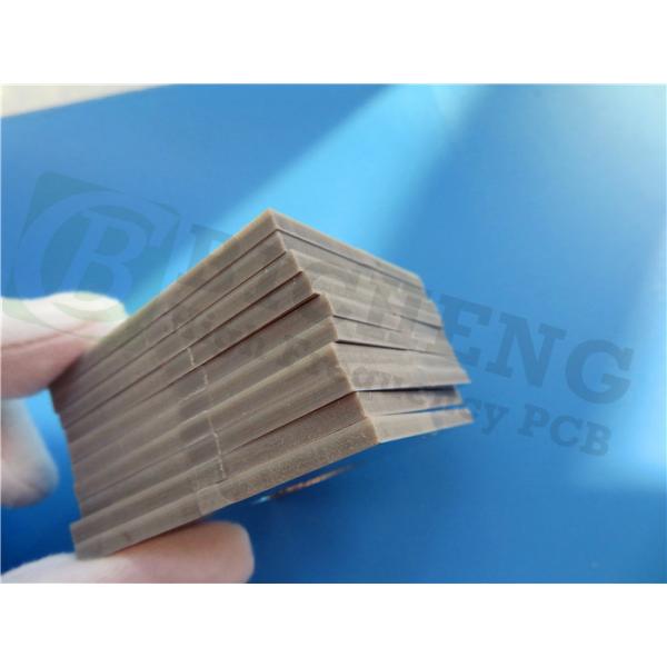
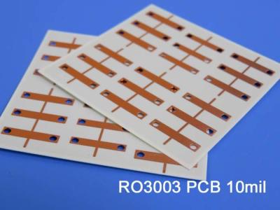
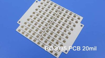
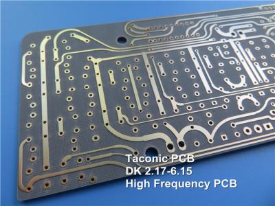
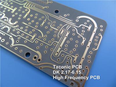
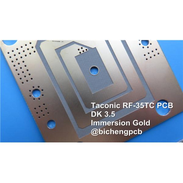
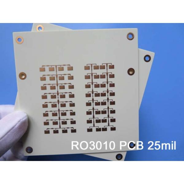
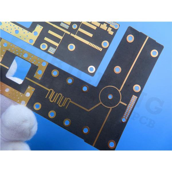
Introducing the RF PCB built on 20mil TMM10i laminates. The TMM10i material is an outstanding choice for high-performance strip-line and micro-strip applications, offering reliability and precision. Engineered with Rogers TMM 10i isotropic thermoset microwave material, this ceramic thermoset polymer composite combines the best features of ceramic and PTFE substrates while enabling flexible processing techniques.
Key Features:
Isotropic dielectric constant (Dk) for consistent performance
Low dissipation factor of .0020 at 10GHz
Thermal coefficient of Dk (-43 ppm/°K) matched to copper
High decomposition temperature (Td) of 425 °C TGA
Excellent thermal conductivity of 0.76W/mk
Thickness range: .0015 to .500 inches (+/- .0015”)
Benefits:
Superior resistance to creep and cold flow for enhanced mechanical properties
Exceptional resistance to process chemicals, minimizing damage during fabrication
Sodium napthanate treatment not required prior to electroless plating
Reliable wire-bonding facilitated by the thermoset resin composition.
TMM10i Typical Value | ||||||
Property | TMM10i | Direction | Units | Condition | Test Method | |
Dielectric Constant,εProcess | 9.80±0.245 | Z | 10 GHz | IPC-TM-650 2.5.5.5 | ||
Dielectric Constant,εDesign | 9.9 | - | - | 8GHz to 40 GHz | Differential Phase Length Method | |
Dissipation Factor (process) | 0.002 | Z | - | 10 GHz | IPC-TM-650 2.5.5.5 | |
Thermal Coefficient of dielectric constant | -43 | - | ppm/°K | -55℃-125℃ | IPC-TM-650 2.5.5.5 | |
Insulation Resistance | >2000 | - | Gohm | C/96/60/95 | ASTM D257 | |
Volume Resistivity | 2 x 10⁸ | - | Mohm.cm | - | ASTM D257 | |
Surface Resistivity | 4 x 10⁷ | - | Mohm | - | ASTM D257 | |
Electrical Strength(dielectric strength) | 267 | Z | V/mil | - | IPC-TM-650 method 2.5.6.2 | |
Thermal Properties | ||||||
Decompositioin Temperature(Td) | 425 | 425 | ℃TGA | - | ASTM D3850 | |
Coefficient of Thermal Expansion - x | 19 | X | ppm/K | 0 to 140 ℃ | ASTM E 831 IPC-TM-650, 2.4.41 | |
Coefficient of Thermal Expansion - Y | 19 | Y | ppm/K | 0 to 140 ℃ | ASTM E 831 IPC-TM-650, 2.4.41 | |
Coefficient of Thermal Expansion - Z | 20 | Z | ppm/K | 0 to 140 ℃ | ASTM E 831 IPC-TM-650, 2.4.41 | |
Thermal Conductivity | 0.76 | Z | W/m/K | 80 ℃ | ASTM C518 | |
Mechanical Properties | ||||||
Copper Peel Strength after Thermal Stress | 5.0 (0.9) | X,Y | lb/inch (N/mm) | after solder float 1 oz. EDC | IPC-TM-650 Method 2.4.8 | |
Flexural Strength (MD/CMD) | - | X,Y | kpsi | A | ASTM D790 | |
Flexural Modulus (MD/CMD) | 1.8 | X,Y | Mpsi | A | ASTM D790 | |
Physical Properties | ||||||
Moisture Absorption (2X2) | 1.27mm (0.050") | 0.16 | - | % | D/24/23 | ASTM D570 |
3.18mm (0.125") | 0.13 | |||||
Specific Gravity | 2.77 | - | - | A | ASTM D792 | |
Specific Heat Capacity | 0.72 | - | J/g/K | A | Calculated | |
Lead-Free Process Compatible | YES | - | - | - | - |
PCB Stackup:
This PCB stackup consists of a 2-layer rigid PCB design. It features copper_layer_1 with a thickness of 35 μm, a Rogers TMM10i Core measuring 0.508 mm (20mil) in thickness, and copper_layer_2 with a thickness of 35 μm. This stackup ensures structural integrity and optimal performance for the PCB.
PCB Construction Details:
This PCB has a compact size, with board dimensions measuring 60mm x 70 mm (+/- 0.15mm). It supports precise circuitry with a minimum trace/space requirement of 8/8 mils, allowing for intricate designs. The minimum hole size is 0.3mm, providing flexibility for component placement.
The finished board thickness is 0.6mm, ensuring a slim profile while maintaining durability. The outer layers have a copper weight of 1oz (1.4 mils), allowing for efficient conduction. The via plating thickness is 20 μm, enabling reliable interconnectivity.
To protect the PCB and enhance its performance, the surface finish is Immersion Gold. However, there is no top or bottom silkscreen or solder mask, allowing for a clean and minimalistic appearance. Each PCB undergoes a thorough 100% electrical test before shipment to ensure quality and functionality.
PCB Material: | Ceramic, Hydrocarbon, Thermoset Polymer Composites |
Designation: | TMM10i |
Dielectric constant: | 9.80 ±0.245 |
Layer count: | Double Layer, Multilayer, Hybrid PCB |
Copper weight: | 0.5oz (17 µm), 1oz (35µm), 2oz (70µm) |
Laminate thickness: | 15mil (0.381mm), 20mil (0.508mm), 25mil (0.635mm), 30mil(0.762mm), 50mil (1.27mm), 60mil (1.524mm), 75mil(1.905mm), 100mil (2.54mm), 125mil (3.175mm), 150mil (3.81mm), 200mil (5.08mm), 250mil (6.35mm), 275mil (6.985mm), 300mil (7.62mm), 500mil (12.70mm) |
PCB size: | ≤400mm X 500mm |
Solder mask: | Green, Black, Blue, Yellow, Red etc. |
Surface finish: | Bare copper, HASL, ENIG, Immersion tin, OSP, Pure Gold Plated (No Nickle under gold) etc.. |
PCB Statistics:
This PCB consists of 8 components, providing versatility for various applications. It features a total of 18 pads, including 11 thru-hole pads and 7 top surface mount technology (SMT) pads. There are no bottom SMT pads present. Additionally, the PCB has 9 vias and 2 nets, allowing for efficient signal routing and connectivity.
Artwork Supplied:
The artwork for this PCB is provided in Gerber RS-274-X format, a widely used industry standard for PCB manufacturing. This format ensures compatibility and accuracy during the fabrication process.
Quality Standard and Availability:
This PCB adheres to the IPC-Class-2 quality standard, ensuring high-quality manufacturing and reliability. It is available for purchase worldwide, making it accessible to customers globally.
Applications:
The TMM10i PCB finds application in various fields, including:
- RF and microwave circuitry
- Power amplifiers and combiners
- Filters and couplers
- Satellite communication systems
- Global Positioning Systems Antennas
- Patch Antennas
- Dielectric polarizers and lenses
- Chip testers
With its superior performance and compatibility, the TMM10i PCB is suitable for a wide range of high-frequency electronic applications, empowering engineers and designers to achieve optimal results.