Introduction
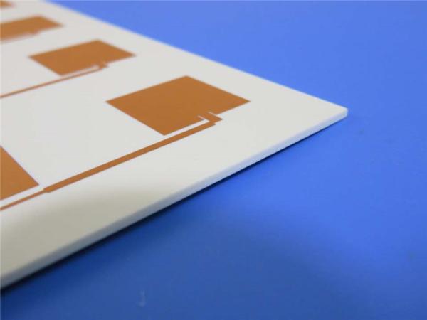
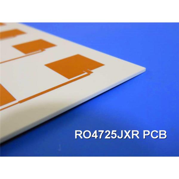
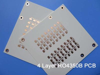
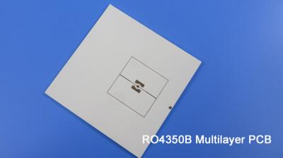
In the ever-evolving world of wireless communications, the demand for high-performance, cost-effective antenna solutions has never been greater. Rogers Corporation, a renowned leader in advanced circuit materials, has developed the RO4725JXR PCB to address this need. This 2-layer rigid circuit board leverages the company's innovative RO4725JXR hydrocarbon/ceramic/woven glass laminate material, offering an affordable and reliable alternative to traditional PTFE-based laminates.
Features and Benefits
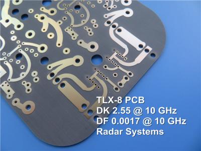
The RO4725JXR PCB boasts an impressive array of features that make it a standout choice for antenna and RF applications. Featuring a dielectric constant (Dk) of 2.55 ± 0.05 at 10 GHz, this material delivers exceptional electrical performance, with a low dissipation factor (Df) of 0.0026 at 10 GHz and 0.0022 at 2.5 GHz. This combination of low loss and stable Dk ensures that antenna designers can achieve substantial gain values while minimizing signal degradation.
One of the RO4725JXR's key advantages is its excellent thermal coefficient of dielectric constant, rated at +34 ppm/°C. This remarkable stability ensures consistent circuit performance across a wide range of environmental conditions, a critical factor for mission-critical applications. Furthermore, the material's CTE is closely matched to copper, with X, Y, and Z axes of 13.9, 19, and 25.6 ppm/°C, respectively, minimizing the risk of delamination and other reliability issues.
In addition to its impressive electrical and thermal properties, the RO4725JXR PCB also boasts a high Tg value of greater than 280°C, making it compatible with standard FR-4 and lead-free assembly processes. This allows for seamless integration into existing manufacturing workflows, reducing the need for specialized handling and processing.
Notably, the RO4725JXR PCB has demonstrated excellent passive intermodulation (PIM) performance, with values better than -160 dBc (43 dBm 1,900 MHz signal). This low PIM characteristic is crucial for cellular base station antennas and other high-performance RF systems, where clean signal integrity is of paramount importance.
Property | RO4725JXR | Direction | Units | Condition | Test Method |
Dielectric Constant, εr Process | 2.55 ± 0.05 | Z | 10 GHz/23°C | IPC-TM-650, 2.5.5.5 | |
Dielectric Constant, εr Design | 2.64 | Z | 1.7 GHz - 5 GHz | Differential Phase Length Method | |
Dissipation Factor | 0.0026 | Z | 10 GHz/23°C | IPC-TM-650, 2.5.5.5 | |
0.0022 | 2.5GHz | ||||
Thermal Coefficient of εr | +34 | Z | ppm/°C | -50°C to 150°C | IPC-TM-650, 2.5.5.5 |
Volume Resistivity (0.030") | 2.16 X 10^8 | MΩ•cm | COND A | IPC-TM-650, 2.5.17.1 | |
Surface Resistivity (0.030") | 4.8 X 10^7 | MΩ | COND A | IPC-TM-650, 2.5.17.1 | |
PIM | -166 | dBc | 50 ohm 0.060” | 43dBm 1900MHz | |
Electrical Strength (0.030”) | 630 | Z | V/mil | IPC-TM-650, 2.5.6.2 | |
Flexural Strength MD | 121 (17.5) | MPa (kpsi) | RT | ASTM D790 | |
CMD | 92 (13.3) | ||||
Dimensional Stability | <0.4 | X,Y | mm/m | after etch +E2/150°C | IPC-TM-650, 2.4.39A |
Coefficient of Thermal Expansion | 13.9 | X | ppm/°C | -55 TO 288°C | IPC-TM-650, 2.1.24 |
19.0 | Y | ||||
25.6 | Z | ||||
Thermal Conductivity | 0.38 | Z | W/mK° | 50°C | ASTM D5470 |
Moisture Absorption | 0.24% | % | 48/50 | IPC-TM-650 2.6.2.1 ASTM D570 | |
Tg | >280 | °C | IPC-TM-650 2.4.24 | ||
Td | 439 | °C | ASTM D3850 | ||
Density | 1.27 | gm/cm3 | ASTM D792 | ||
Copper Peel Strength | 8.5 | pli | 1 oz LoPro EDC | IPC-TM-650 2.4.8 | |
Flammability | N/A | UL94 | |||
Lead-Free Process Compatible | YES |
Applications and Specifications
The RO4725JXR PCB is ideally suited for a wide range of antenna and RF applications, with a particular focus on cellular base station antennas. Its combination of low loss, stable Dk, and low PIM make it an excellent choice for designers seeking to optimize both cost and performance in their wireless solutions.
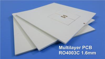
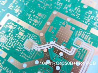
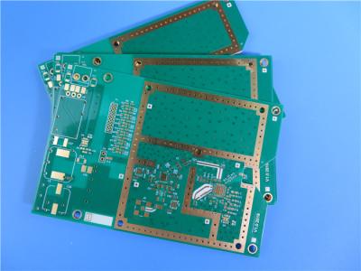
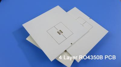
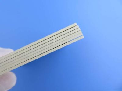
In terms of specifications, this PCB is a 2-layer rigid circuit board with dimensions of 42.13 mm x 112.96 mm ± 0.15 mm. The copper thickness is 1 oz (1.4 mil) on both outer layers, and the minimum trace/space is 5/5 mil. The board features a minimum hole size of 0.4 mm and a finished thickness of 0.8 mm, with a via plating thickness of 20 μm. The surface finish is immersion gold, and the board is manufactured to the IPC-Class-2 quality standard, with 100% electrical testing prior to shipment.
Conclusion
The Rogers RO4725JXR PCB represents a compelling alternative to traditional PTFE-based laminates, offering a unique blend of exceptional RF performance, thermal stability, and cost-effectiveness. With its robust features and consistent circuit behavior, this PCB is poised to become a go-to solution for antenna designers and RF engineers seeking to optimize their wireless systems.
PCB Capability (TMM10) | |
PCB material: | Hydrocarbon / Ceramic / Woven Glass |
Designation: | RO4725JXR |
Dielectric constant: | 2.55 |
Layer count: | Sinlge-sided PCB, Double-sided PCB, Multi-layer PCB, Hybrid PCB |
Dielectric thickness: | 30.7mil(0.780mm), 60.7mil (1.542mm) |
Copper weight: | 1oz (35µm), 2oz (70µm) |
PCB size: | ≤400mm X 500mm |
Solder mask: | Green, Black, Blue, Red, Yellow, White etc. |
Surface finish: | Immersion gold, HASL, Immersion silver, Immersion tin, Bare copper, OSP, ENEPIG, Pure gold etc.. |