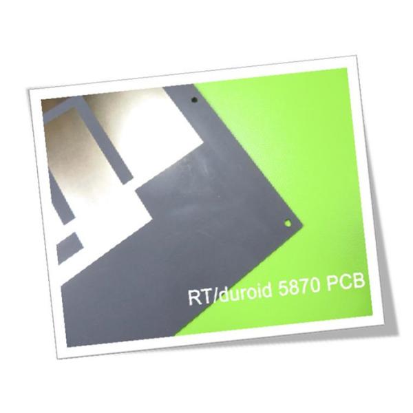
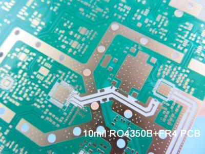
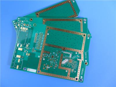
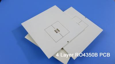
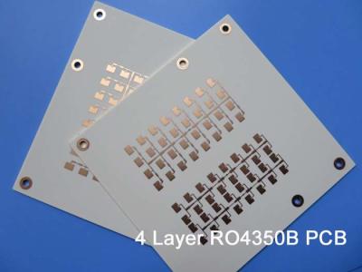
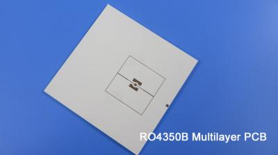
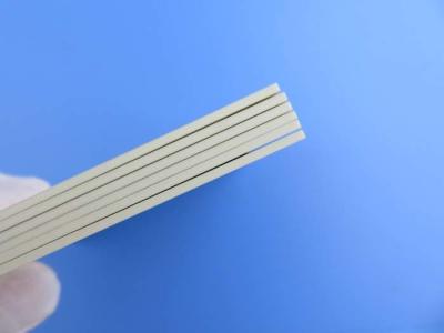
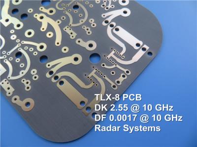
Today, we're glad to introduce a newly shipped PCB base on the RT duroid 5870 laminates. The Rogers RT/duroid 5870 high frequency laminate is a PTFE composite material reinforced with glass microfibers. It offers a low dielectric constant (Dk) of 2.33 with tight tolerance, making it well-suited for high frequency and broadband applications where low dispersion and losses need to be minimized.
RT duroid 5870 PCB features a dielectric constant of 2.33 ± 0.02 at 10 GHz and 23°C, and a dissipation factor of 0.0012 at 10 GHz and 0.0005 at 1 MHz. It also boasts a strong copper peel strength of 27.2 pli, low moisture absorption of 0.02%, and high thermal stability with a Td greater than 500°C. The material is isotropic and has a UL 94-V0 flammability rating.
The benefits of this RT/duroid 5870 PCB include the lowest electrical loss for a reinforced PTFE material, easy machinability, resistance to solvents and reagents used in etching or plating, and suitability for high moisture environments. It is a well-established and reliable material with uniform electrical properties over a wide frequency range.
This PCB itself is a 2-layer rigid construction, with 35 μm of copper on both layers and a 0.127 mm (5 mil) dielectric thickness of RT/duroid 5870. The board dimensions are 46.7 mm x 67.02 mm, with a tolerance of ±0.15 mm. It features a minimum trace/space of 4/4 mils, minimum hole size of 0.3 mm, and a finished board thickness of 0.2 mm. The copper weight is 1 oz (1.4 mils) on the outer layers, and the via plating thickness is 20 μm. The surface finish is immersion gold, and each PCB undergoes 100% electrical testing prior to shipment.
This RT/duroid 5870 PCB is well-suited for a variety of high-frequency and broadband applications, including commercial airline broadband antennas, microstrip and stripline circuits, millimeter wave applications, radar systems, guidance systems, and point-to-point digital radio antennas.
RT/duroid 5870 Typical Value | ||||||
Property | RT/duroid 5870 | Direction | Units | Condition | Test Method | |
Dielectric Constant,εProcess | 2.33 2.33±0.02 spec. | Z | N/A | C24/23/50 C24/23/50 | 1 MHz IPC-TM-650 2.5.5.3 10 GHz IPC-TM 2.5.5.5 | |
Dielectric Constant,εDesign | 2.33 | Z | N/A | 8GHz to 40 GHz | Differential Phase Length Method | |
Dissipation Factor,tanδ | 0.0005 0.0012 | Z | N/A | C24/23/50 C24/23/50 | 1 MHz IPC-TM-650 2.5.5.3 10 GHz IPC-TM 2.5.5.5 | |
Thermal Coefficient of ε | -115 | Z | ppm/℃ | -50℃to 150℃ | IPC-TM-650 2.5.5.5 | |
Volume Resistivity | 2 x 10⁷ | Z | Mohm cm | C/96/35/90 | ASTM D 257 | |
Surface Resistivity | 3 x 10⁷ | Z | Mohm | C/96/35/90 | ASTM D 257 | |
Specific Heat | 0.96(0.23) | N/A | j/g/k (cal/g/c) | N/A | Calculated | |
Tensile Modulus | Test at 23℃ | Test at 100℃ | N/A | MPa(kpsi) | A | ASTM D 638 |
1300(189) | 490(71) | X | ||||
1280(185) | 430(63) | Y | ||||
Ultimate Stress | 50(7.3) | 34(4.8) | X | |||
42(6.1) | 34(4.8) | Y | ||||
Ultimate Strain | 9.8 | 8.7 | X | % | ||
9.8 | 8.6 | Y | ||||
Compressive Modulus | 1210(176) | 680(99) | X | MPa(kpsi) | A | ASTM D 695 |
1360(198) | 860(125) | Y | ||||
803(120) | 520(76) | Z | ||||
Ultimate Stress | 30(4.4) | 23(3.4) | X | |||
37(5.3) | 25(3.7) | Y | ||||
54(7.8) | 37(5.3) | Z | ||||
Ultimate Strain | 4 | 4.3 | X | % | ||
3.3 | 3.3 | Y | ||||
8.7 | 8.5 | Z | ||||
Moisture Absorption | 0.02 | N/A | % | 0.62"(1.6mm) D48/50 | ASTM D 570 | |
Thermal Conductivity | 0.22 | Z | W/m/k | 80℃ | ASTM C 518 | |
Coefficient of Thermal Expansion | 22 28 173 | X Y Z | ppm/℃ | 0-100℃ | IPC-TM-650 2.4.41 | |
Td | 500 | N/A | ℃ TGA | N/A | ASTM D 3850 | |
Density | 2.2 | N/A | gm/cm3 | N/A | ASTM D 792 | |
Copper Peel | 27.2(4.8) | N/A | Pli(N/mm) | 1oz(35mm)EDC foil after solder float | IPC-TM-650 2.4.8 | |
Flammability | V-0 | N/A | N/A | N/A | UL 94 | |
Lead-free Process Compatible | Yes | N/A | N/A | N/A | N/A |
High-Performance RF/Microwave PCB: The Rogers RT/duroid 5870 Advantage
In the ever-evolving world of high-frequency and broadband electronics, the choice of printed circuit board (PCB) material can make or break a design. One material that has long been a go-to solution for demanding RF and microwave applications is Rogers' RT/duroid 5870 high-frequency laminate.
This PTFE-based composite material, reinforced with glass microfibers, offers a unique combination of electrical, mechanical, and thermal properties that make it an ideal choice for a wide range of high-frequency circuits and systems.
Exceptional Electrical Performance
At the heart of the RT/duroid 5870's appeal is its outstanding electrical performance. The material boasts a low dielectric constant (Dk) of 2.33 ± 0.02 at 10 GHz and 23°C, ensuring excellent signal integrity and minimal dispersion even at higher frequencies.
Equally impressive is the laminate's low dissipation factor (Df) of just 0.0012 at 10 GHz and 0.0005 at 1 MHz. This translates to remarkably low energy losses, which is crucial for maximizing efficiency and signal fidelity in high-speed, high-frequency applications.
The material's electrical properties also remain remarkably stable over a wide frequency range, from DC up to 100 GHz and beyond. This isotropic behavior is a key advantage, as it allows designers to use the same material for different circuit topologies without having to worry about unpredictable performance variations.
Mechanical Robustness and Reliability
In addition to its superior electrical characteristics, the RT/duroid 5870 also excels in terms of mechanical properties. The material boasts a strong copper peel strength of 27.2 pli, providing robust attachment of copper layers and ensuring reliable interconnections.
Its low moisture absorption of just 0.02% makes the laminate well-suited for use in high-moisture environments, while the material's high thermal stability (Td > 500°C) and UL 94-V0 flammability rating add an extra layer of reliability and safety.
The glass microfiber reinforcement also gives the RT/duroid 5870 exceptional dimensional stability, with a coefficient of thermal expansion (CTE) of 22 ppm/°C in the X-axis, 28 ppm/°C in the Y-axis, and 173 ppm/°C in the Z-axis. This helps to minimize registration issues and ensure dimensional integrity, even in complex, high-density designs.
Design Flexibility and Machinability
One of the key advantages of the RT/duroid 5870 is its excellent machinability, which allows designers to easily cut, shape, and machine the material to fit their specific requirements. This flexibility is particularly valuable in prototyping and low-volume production, where the ability to quickly iterate on design concepts can be a game-changer.
The laminate's resistance to the solvents and reagents used in etching and plating processes further enhances its versatility, enabling the use of standard PCB fabrication techniques without compromising performance or reliability.
Broad Application Scope
The exceptional electrical, mechanical, and thermal properties of the RT/duroid 5870 make it a versatile solution for a wide range of high-frequency and broadband applications, including:
Commercial airline broadband antennas
Microstrip and stripline circuits
Millimeter-wave systems
Radar and guidance systems
Point-to-point digital radio antennas
Whether you're working on cutting-edge 5G infrastructure, next-generation satellite communications, or high-resolution radar systems, the Rogers RT/duroid 5870 can provide the performance, reliability, and design flexibility you need to stay ahead of the curve.
Conclusion
In the fast-paced world of high-frequency electronics, the choice of PCB material can be a critical factor in the success of a design. The Rogers RT/duroid 5870 high-frequency laminate stands out as a premier solution, offering unparalleled electrical performance, mechanical robustness, and design flexibility. By leveraging the unique advantages of this material, engineers and designers can push the boundaries of what's possible in the realm of RF and microwave technology.