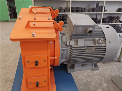
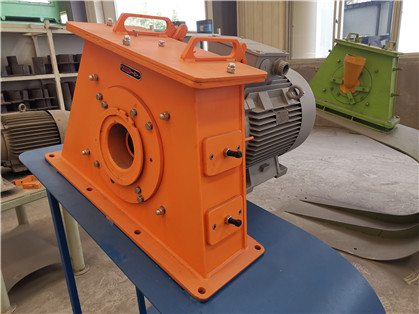
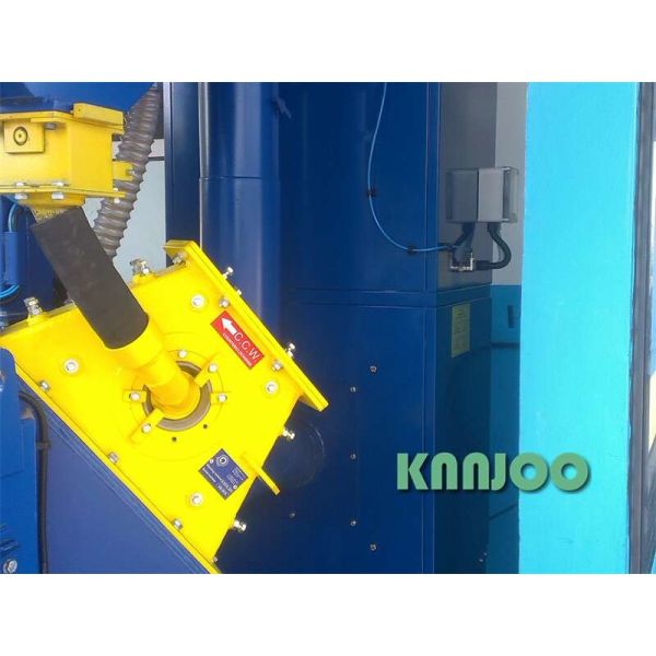
New Design Direct Coupling Blast Wheel Used On Different Shot Blast Machines can make uniform metallic luster
After years of research and development and technical cooperation with German companies, the company has produced a high-power direct-coupled shaft 7.5-75Kw high-efficiency shot blasting machine, breaking the European and American high-power direct-connection shot blasting technology monopoly. This shot blasting machine is the highest-end technology in Asia and is a key component of various shot blasting equipment. It is widely used for sand falling of castings, surface cleaning of castings, forgings, welded parts, heat-treated parts, and surface pretreatment of various profiles. Processing, and surface strengthening process of gears, springs and other mechanical parts. This direct-shaft shot blasting technology is one of the important advances in the development history of China's shot blasting equipment. The shot blasting machine also has the following characteristics:
1 The shot blasting machine and the motor adopt the German THYSSENKRUPP ThyssenKrupp technology. Compared with the old-fashioned shot blasting machine, the friction loss is reduced. Not only the motor efficiency is greatly improved by 20%, the failure points are also fewer, and the maintenance cost is reduced by 50%. .
2 Compared with the old shot blasting machine, the volume is smaller, the angle can be arranged at will, and the maintenance is more convenient.
3 Compared with the old-fashioned shot blasting machine, the shot blasting effect is constant, and the cleaning quality will not fluctuate.
4 The blades and wear parts are made of high chromium investment casting Cr27, which has high wear resistance, and the service life is about 800-4000 hours, which is 3 times that of ordinary casting materials;
5 Shot blaster impeller: The impeller is carburized with wear-resistant alloy. The impeller body is processed at one time by a high-precision CNC machining center with high precision, ensuring the balance of high-speed operation, low vibration, low noise, and long life;
6 The bearing adopts the products of Sweden SKF;
7 The motor adopts Siemens products;
1. Semi-automatic flow control system, used to control the flow of shot material entering the shot blaster, and manually adjust the flow of steel shot 2. Fully sealed structure design, with lockable inspection opening, equipped with two bearings. 3. The upper end of each flow valve is equipped with a manual shut-off valve. If the flow valve needs to be repaired, it can be closed to close the pellets flowing from the silo for easy maintenance. |
Structure: Compared with the old belt blast wheel, the shot blasting speed is constant, there is no uneven cleaning or strengthening effect caused by belt slippage, and the cleaning quality will not fluctuate. The efficiency of this shot blasting machine is as high as 20kg/min•kW, and the energy consumption is 20% lower than that of the ordinary shot blasting machine.Compound projection belt: In order to completely clean the yin and yang, convex and concave surfaces of the workpiece, the shot blasting blade has a wider projection area, and the width of the horizontal projection belt is 1.5~2 times that of the conventional shot blasting machine.
Material and technology: long working life of wearing parts: The wear parts of this blast wheel are made of Cr28% high chromium wear-resistant cast iron melt film precision casting, and the service life is more than 3 times that of tidal sand castings. The manganese steel shells of all blast wheel are processed by a large gantry CNC milling machine at one time;
Blast wheel impeller: The impeller body is carburized with wear-resistant alloy. The impeller body is processed at one time by a high-precision CNC machining center with high precision. Compared with other simple processes, it has obvious advantages, ensuring the balance of high-speed operation, low vibration, low noise, and long life;
1. Feeding door
The feeding door is welded with a steel structure. The protection of the feeding door is made of high manganese steel guard plate. The protection is labyrinth type. The transmission form is electric chain trolley drive (with safety pin), with detection device switch to detect the position of the door.
2. Feeding machine
The feeding machine is composed of a bracket, a trolley and a chain drive mechanism. There are protective plates on both sides of the bracket, and a control button is installed on one side. The bracket supports a pair of swing rods. When the feeding driving device is driven, the material bucket rises along the inner groove of the swing rod, and at the same time, the swing rod rotates around the support point , Make the material hopper incline towards the feeding door of the cleaning machine during the ascent and rotation, and dump the material into the drum.
There is a rotary proximity switch at the end of the drive shaft to limit the rising end of the hopper. After the hopper descends, a final material proximity switch gives a signal to indicate the completion of the action.
1. A set of mesh separator is connected to the elevator, located at the upper end of the magnetic separator. The fine materials are filtered and separated by the mesh screen and then sent to the magnetic separator. The coarse materials and impurities are conveyed through the mesh screen spirally to the tail port. The outlet pipe is discharged.
2. Used to finely separate qualified shots, broken shots and dust to ensure the uniformity of shots.
3. Welded structure, there are multiple well-designed cells inside for wind flow. The front is an openable inspection door for daily observation and maintenance. An air inlet is provided on the door to provide air medium for separating dust.
4. Multi-pole baffle structure, adjustable. Used to adjust the uniformity of the sand curtain.
5. Two static magnets are installed on the upper and lower sides, which can finely separate qualified shots and broken steel shots to ensure the uniformity of the medium used for shot blasting.
6. The silo is connected below. After sorting, the qualified shots flow through the silo for storage, ready to be reused.
1. Two sets of grating induction devices are installed at the inlet and outlet respectively. The grating density can be selected according to the size of the workpiece and used in pairs.
2. When the workpiece enters the shot blasting chamber, the grating at the feed port will sense the incoming workpiece, and the shot blasting device will start with a delay. A grating induction device will be installed at the discharge port. When the incoming and outgoing grating senses that no workpiece is coming out, the flow valve will automatically close immediately to prevent the phenomenon of empty throwing.