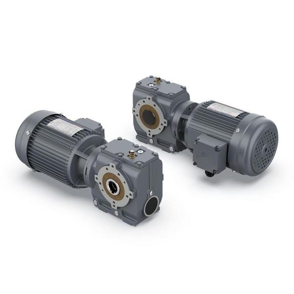
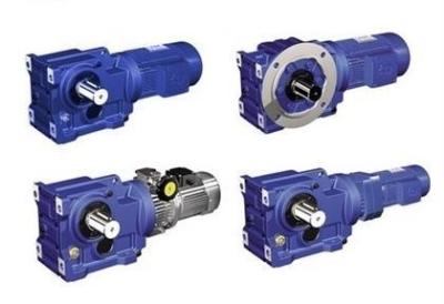
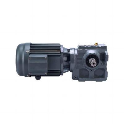
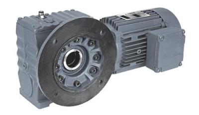
our high-efficiency helical-worm gear units featuring a simple yet effective design. The accompanying figure showcases a gearmotor integrated with a helical-worm gear unit, emphasizing its cost-effectiveness.
The ability to individually adjust torque and speed facilitates space-saving installations of our helical-worm gear units. Available in various configurations, including double, triple, quadruple, and quintuple reduction units, they can be mounted on foot, flange, or shaft. Choose from motorised, motor-ready, or reducer options with a keyed input shaft for added versatility.
Experience the convenience and efficiency of our helical-worm gear units, tailored for diverse industrial applications.
Feature
1. Compact structure, modular design
2. High efficiency of the gear units of over 90%
3. Long service life
4. Multi-stage(2 or 3 stages) gear units for low output speed
5. Hollow output shaft with keyed connection, shrink disk, splined hollow shaft, or torque arm
6. Can be combined with other types of gearboxes (Such as R Series, UDL Series)
Main Application Industries
1.Food light industry, electrical machinery, engineering machinery, metallurgical machinery;
2.Cement machinery, environmental protection machinery, electronic appliances, road construction machinery;
3.Water conservancy machinery, chemical machinery, mining machinery, transportation machinery;
4.Building materials machinery, rubber machinery, petroleum machinery and other industries.
Specification :
Gear material | 20CrMnTi alloy steel |
Surface hardness of gears | HRC58°~62° |
Gear core hardness | HRC33~40 |
Input/Output shaft material | 42CrMo alloy steel |
Input /Output shaft hardness | HRC25~30 |
Machining precision of gears | Accurate grinding,6~5 Grade |
Lubricating oil | GB L-CKC220-460,Shell Omala220-460 |
Heat treatment | Tempering,cementiting,quenching,etc. |
Eficiency | 94%~96%(depends on the trans mis sion stage) |
Noise (MAX) | 60~68dB |
Temp.rise(MAX) | 40℃ |
Temp.rise (Oil)(MAX) | 50°℃ |
Vibration | s20μm |
Backlash | s20Arcmin |
Brand of bearings | China top brand bearing,or other brands requested |
SIZE | Shaft Dia. (mm) | Center Height | Output Flange Dia. (mm) | Power (kw) | Ratio | Permissible Torque(N.m) | Weight (kgs) | |
Solid Hallow | ||||||||
37 | φ20k6 | φ20h7 | 82 | φ120/160 | 0.18-0.75 | 10.27-165.71 | 90 | 7 |
47 | φ25k6 | φ25h7 | 100 | φ160 | 0.18-1.50 | 11.46-244.74 | 170 | 10 |
57 | φ30k6 | φ30h7/35h7 | 180 | φ200 | 0.18-3.0 | 10.78-196.21 | 300 | 14 |
67 | φ35k6 | φ40h7/45h7 | 140 | φ200 | 0.25-5.50 | 11.55-227.20 | 520 | 26 |
77 | φ45k6 | φ50h7/60h7 | 180 | φ250 | 0.55-7.50 | 9.96-241.09 | 1270 | 50 |
87 | φ60m6 | φ60h7/70h7 | 225 | φ350 | 0.75-15.0 | 11.83-223.26 | 2280 | 100 |
97 | φ70m6 | φ70h7/90h7 | 280 | φ450 | 1.50-22.0 | 12.5-230.48 | 4000 | 170 |
Why choose us :
Quality Control Standards
1. Body / Box Body
(1) The section of the cover and the body shall be smooth and smooth to ensure tight assembly. Check the contact tightness of the section, that is, the insertion depth of the plug ruler less than 0.05mm shall not be greater than 1 / 3 of the section.
(2) The upper cover and the body shall not crack, and the kerosene inspection shall not contain leakage.
2. Dute Line Cylindrical Gear
(1) The gear shall not have defects in burrs, cracks, fractures, etc.
(2) gear engagement that the tooth height and tooth width is not greater than 20%.
(3) gear must be correctly engaged after assembly and its contact area shall meet the provisions in Table 1.
(4) The side clearance of gear engagement shall meet specified in Table 2.
(5) The top gap of the gear engagement is 0.2~0.3m (m is the normal modulus).
(6) Check the side and top clearance of the gear by pressure lead method and if not in accordance with Articles (4) and (5), the center distance may be corrected in Table 2 and (5)
(7) The center distance limit deviation of both gears shall meet the provisions in Table 3.
(8)The parallelism of the gear centerline on the tooth width is not greater than that specified in Table 4
(9)The radial beat of the gear rim shall not be greater than that specified in Table 5
(10)The maximum allowable wear value of tooth thickness at the gear section circle shall meet Table 6.
3. Bevel Gear Wheel
(1) The gear must be smooth without burrs, scars, cracks, etc.
(2) The limit deviation of the clip angle of the gear shaft is specified in Table 7.
(3) The displacement of gear centerline shall not be greater than specified in Table 8 and the displacement inspection method is shown in FIG. 4.
(4) The side gap of gear engagement shall meet the provisions in Table 9
(5) Top gap of gear engagement is 0.2~0.3m.(The m is the large-end module number)
(6) The displacement of the gear cone shall not be greater than that specified in Table 10