Product Introduction
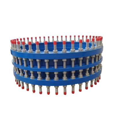
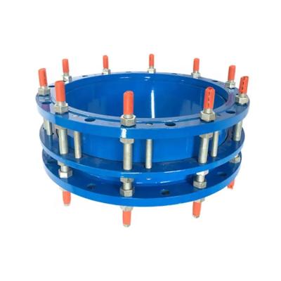
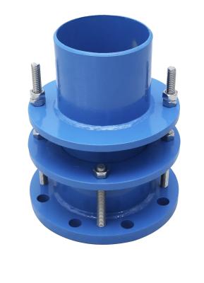
The dismantling joint consists of the main body, the sealing ring, the gland, the telescopic short pipe and other main parts. It is a new product that connects pumps, valves and other equipment with pipelines. It connects them into a whole through full bolts, and has a certain displacement. In this way, it can be adjusted according to the installation size on site during installation and maintenance, and the axial thrust can be transferred back to the whole pipeline during work. This not only improves work efficiency, but also plays a certain protective role for pumps, valves and other equipment.
Product Advantages
1. Good chemical and thermal stability
2. Good anti-friction and self-lubrication
3. Good sealing performance
4. Ease of installation and maintenance
5. Wide range of application
Product parameters
DN | PN10 | PN16 | ||||||||||
D | K | Bolt holes | L | H | D | K | Bolt holes | L | H | |||
Bolt | N-φd2 | Bolt | N-φd2 | |||||||||
40 | 150 | 110 | M16 | 4-19 | 180 | 330 | 150 | 110 | M16 | 4-19 | 180 | 330 |
50 | 165 | 125 | M16 | 4-19 | 180 | 330 | 165 | 125 | M16 | 4-19 | 180 | 330 |
65 | 185 | 145 | M16 | 4-19 | 180 | 330 | 185 | 145 | M16 | 4-19 | 180 | 330 |
80 | 200 | 160 | M16 | 8-19 | 200 | 350 | 200 | 160 | M16 | 8-19 | 200 | 350 |
100 | 220 | 180 | M16 | 8-19 | 200 | 350 | 220 | 180 | M16 | 8-19 | 200 | 350 |
125 | 250 | 210 | M16 | 8-19 | 200 | 350 | 250 | 210 | M16 | 8-19 | 200 | 350 |
150 | 285 | 240 | M20 | 8-23 | 200 | 350 | 285 | 240 | M20 | 8-23 | 200 | 350 |
200 | 340 | 295 | M20 | 8-23 | 220 | 380 | 340 | 295 | M20 | 12-23 | 220 | 380 |
250 | 400 | 350 | M20 | 12-23 | 220 | 380 | 400 | 355 | M24 | 12-28 | 230 | 400 |
300 | 455 | 400 | M20 | 12-23 | 220 | 380 | 455 | 410 | M24 | 12-28 | 250 | 420 |
350 | 505 | 460 | M20 | 16-23 | 230 | 400 | 520 | 470 | M24 | 16-28 | 260 | 440 |
400 | 565 | 515 | M24 | 16-28 | 230 | 400 | 580 | 525 | M27 | 16-31 | 270 | 460 |
450 | 615 | 565 | M24 | 20-28 | 250 | 420 | 640 | 585 | M27 | 20-31 | 270 | 460 |
500 | 670 | 620 | M24 | 20-28 | 260 | 450 | 715 | 650 | M30 | 20-34 | 280 | 490 |
600 | 780 | 725 | M27 | 20-31 | 260 | 460 | 840 | 770 | M33 | 20-37 | 300 | 520 |
700 | 895 | 840 | M27 | 24-31 | 260 | 460 | 910 | 840 | M33 | 24-37 | 300 | 520 |
800 | 1015 | 950 | M30 | 24-34 | 290 | 500 | 1025 | 950 | M36 | 24-40 | 320 | 550 |
900 | 1115 | 1050 | M30 | 28-34 | 290 | 500 | 1125 | 1050 | M36 | 28-40 | 320 | 560 |
1000 | 1230 | 1160 | M33 | 28-37 | 290 | 510 | 1255 | 1170 | M39 | 28-43 | 340 | 600 |
1200 | 1455 | 1380 | M36 | 32-40 | 320 | 570 | 1485 | 1390 | M45 | 32-49 | 360 | 650 |
Product installation steps
1. Loosen the pressure plate bolts: Before installation, you need to loosen the pressure plate bolts and pull the product to the installation length.
2. Align the flanges: Align the two flanges, making sure they are parallel and aligned. For the power transmission joint with the inner sleeve, care should be taken to make the direction of the inner sleeve consistent with the direction of the medium flow.
3. Install the sealing gasket: Place the sealing gasket between the two flanges to ensure that the gasket is installed correctly to prevent fluid leakage.
4. Tighten the bolts: Use the diagonal method to tighten the bolts and nuts in turn to make the two flanges tightly connected together. During the tightening process, it should be ensured that the tightening torque of the bolt and nut meets the requirements.
5. Adjust the displacement: Adjust according to the size of the site to ensure that the force transmission joint has a certain amount of displacement, which is convenient to adjust according to the needs during installation and maintenance.
Hot selling products
Single sphere Rubber duckbill Lined with Semi circle mini
rubber joint check valve PTFE bellows type repair clamp
Inventory display
Workshop display