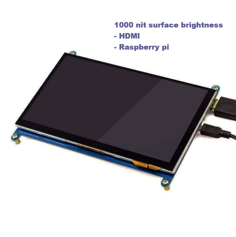
HDMI 7 inch Display, 7 inch PCAP TFT Display
SFRA700H-800480ACT-01 is a HDMI TFT LCD module which integrated TFT LCD, PCAP touch and driving board.
1- The module perfectly presents the HDMI digital signal output from the PC on the 800*480 LCD screen.
2- Support HDMI 1.3, HDMI 1.4, HDCP 1.4, HDCP 2.2 standards. HDMI signal source is compatible with mainstream mini PCs such as Raspberry Pi, BB Black, Banana Pi, etc.
3- TOUCH is from USB to I2C, no need to install drivers.
4- The design is mainly used on the Raspberry Pi display, and it can also be used on other HDMI industrial control small screen touch devices. When used as a Raspberry Pi display, it supports Raspbian, Ubuntu, WIN10 IOT and other systems, single-touch.
5- when used as a computer display, it supports Windows 7/8/10, five-point touch, driver-free.
Version | 01 | ||
Signal supported | HDMI | 480i,480p,576i,576p,720p,1080i,1080p | |
TOUCH | USB standard | ||
VGA | Not support | ||
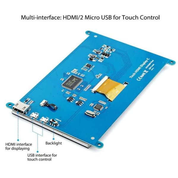
Interface on mainboard | input | HDMI | A type HDMI patch female 19Pin patch (horizontal) |
USB | MICRO 5P USB female B type 5.9MM (horizontal) | ||
Earphone interface | NC | ||
Touch interface | 6 pin | FPC-0.5-6PIN (horizontal) | |
Display interface | RGB 50 pin | FPC-0.5-50PIN (horizontal) | |
Audio | Audio output | 8Ω1.5W | 4PIN-1.25 H1.8 Ultra-thin female seat (horizontal) |
Power supply | Power input | USB input 5V(+/-0.5V) | |
Display Vop | 3.3V | ||
Power operation | Power on display | ||
Mainboard standby power consumption | <0.25W | ||
OSD Menu | Menu (reserve) | Brightness, Contrast, Auto Correction, Phase, Clock, Field Position, Function Setting, Reset, etc. | |
Language(reserve) | Chinese, English, French, German, Italian, Spanish, Russian, Korean, Japanese, etc. | ||
button (reserved) | POWER,MENU,UP,DOWN,EXIT |
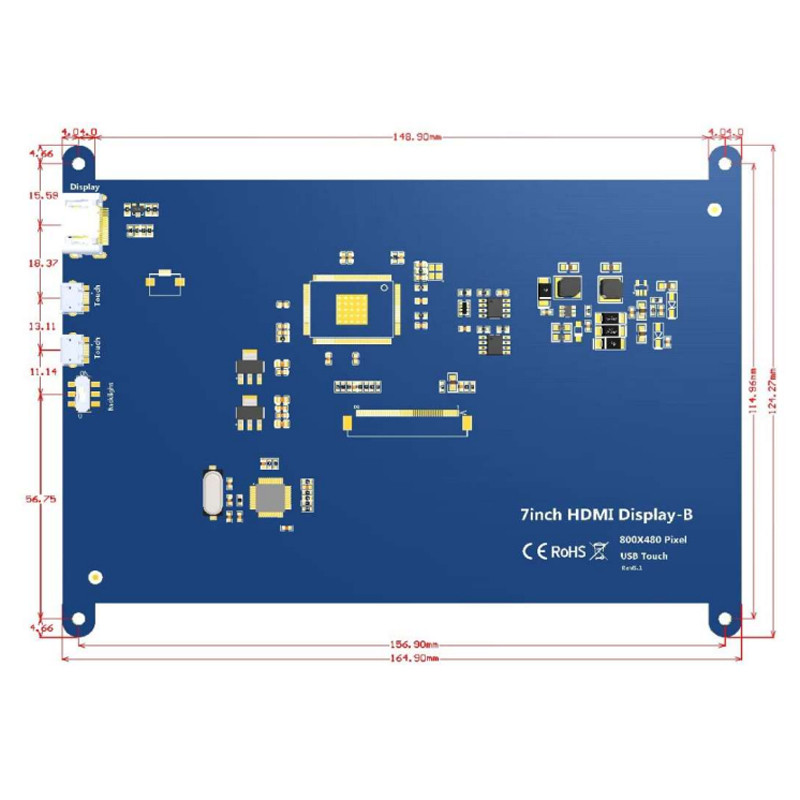
HDMI 7 inch Display, 7 inch PCAP TFT Display Product Image
HDMI interface pin definition
1 | T.M.D.S DATA2+ |
2 | T.M.D.S DATA2 Shielded |
3 | T.M.D.S DATA2- |
4 | T.M.D.S DATA1+ |
5 | T.M.D.S DATA1 Shielded |
6 | T.M.D.S DATA1- |
7 | T.M.D.S DATA0+ |
8 | T.M.D.S DATA0 Shielded |
9 | T.M.D.S DATA0- |
10 | T.M.D.S DATA CLOCK+ |
11 | T.M.D.S DATA CLOCK Shielded |
12 | T.M.D.S DATA CLOCK- |
13 | CEC (Consumer Electronics Control Optional) |
14 | Reserved (in cable but N.C. on device) |
15 | SCL(DDC) |
16 | SDA(DDC) |
17 | DDC/CEC Ground |
18 | +5V (power supply) |
19 | Hot swap probe cable |
USB( 5V ) pin definition
1 | VCC |
2 | NC |
3 | NC |
4 | NC |
5 | GND |
USB TP Pin definition
1 | VCC |
2 | D- |
3 | D+ |
4 | NC |
5 | GND |
Speaker interface Pin Definition
1 | ROUT+ |
2 | ROUT- |
3 | LOUT- |
4 | LOUT+ |
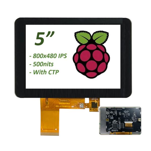
6,LCD pin definition
1 | VLED+
| Power for LED backlight (Anode)
|
2 | VLED+
| Power for LED backlight (Anode)
|
3 | VLED-
| Power for LED backlight (Cathode)
|
4 | VLED-
| Power for LED backlight (Cathode)
|
5 | GND
| Power ground
|
6 | VCOM
| Common voltage
|
7 | DVDD
| Power for Digital Circuit
|
8 | MODE
| DE/SYNC mode select
|
9 | DE
| Data Input Enable
|
10 | VS
| Vertical Sync Input
|
11 | HS
| Horizontal Sync Input
|
12 | B7
| Blue data(MSB)
|
13 | B6
| Blue data
|
14 | B5
| Blue data
|
15 | B4
| Blue data
|
16 | B3
| Blue data
|
17 | B2
| Blue data
|
18 | B1
| Blue data
|
19 | B0
| Blue data(LSB)
|
20 | G7
| Green data(MSB)
|
21 | G6
| Green data
|
22 | G5
| Green data
|
23 | G4
| Green data
|
24 | G3
| Green data
|
25 | G2
| Green data
|
26 | G1
| Green data
|
27 | G0
| Green data(LSB)
|
28 | R7
| Red data(MSB)
|
29 | R6
| Red data
|
30 | R5
| Red data
|
31 | R4
| Red data
|
32 | R3
| Red data
|
33 | R2
| Red data
|
34 | R1
| Red data
|
35 | R0
| Red data(LSB) |
36 | GND
| Power Ground
|
37 | DCLK
| Sample clock
|
38 | GND
| Power Ground
|
39 | L/R
| Left / right selection
|
40 | U/D
| Up/down selection
|
41 | VGH
| Gate ON Voltage
|
42 | VGL
| Gate OFF Voltage
|
43 | AVDD
| Power for Analog Circuit
|
44 | RESET
| Global reset pin.
|
45 | NC
| No connection
|
46 | VCOM
| Common Voltage
|
47 | DITHB
| Dithering function
|
48 | GND
| Power Ground
|
49 | NC
| No connection
|
50 | NC
| No connection
|
Touch panel Pin Definition
1 | VDD | |
2 | GND | |
3 | TP-INT | |
4 | TP-RST | |
5 | TP-SCL | |
6 | TP-SDA |
Requirements for use
In order to ensure the normal use of this product and prevent accidents such as electric shock or fire, please read and understand all the requirements and operating procedures before using this product. The following requirements are strictly observed:
1. The DC power supply required by this product is generated by the AC/DC power adapter, and the AC/DC power adapter should be kept away from the heat source and placed in a well-ventilated place.
2. AC power socket and AC power cord should pay attention to good grounding and can withstand sufficient current demand.
3. The input voltage of the DC power supply required by this product is +5V, the error is not greater than +/-0.5V, and the current is determined according to the selected LED screen and the power of the whole machine.
4. Pay attention to good ventilation and heat dissipation, do not place in a closed non-thermal shell or box, and do not let direct sunlight or other heat sources bake.
5. Pay attention to avoid excessive humidity and excessive dust, so as to avoid circuit corrosion causing failure.
6. When assembling, pay attention to reserve a certain space to provide air convection on the board surface to dissipate heat, and prevent electrical conductors (such as fixed iron plates such as drive boards and high-voltage plates) and components on the board from contacting short circuits.
7. Pay attention to prevent the drive plate from bending and deforming due to additional pressure.
8. When assembling, pay attention to the correct electrical connection of the drive board, LED screen, button board and other components, select the correct LED screen working voltage (too low will show abnormal, too high may burn out the LED screen), check that it is correct before powering on.
9. The program on the driver board should match the corresponding LED screen.
10. Pay attention to electrostatic protection when assembling the board, and pay attention to avoid short circuit and static electricity on the hand to damage the board.
11. All input and output interfaces need to be operated in the case of power failure (plug and unplug connectors).
12. This product is suitable for general commercial use and household, the ambient temperature: -10~+40°C, relative humidity: ≤80%.
13. Unplug the power when not in use for a long time.