COG Module 128X64 Pixel FSTN Positive 3.3v Product Introduction
The 128x64 COG LCD is an extremely widely used low-cost graphic dot matrix module, thanks to its low cost, user friendliness, and ease of programming. SAEFDISPLAY offers over 1000 different sizes (VA) of standard products for customers to choose from, saving them high tooling costs. Please contact our sales team for specifications. The positive FSTN COG LCD can be equipped with backlights of different colors, such as yellow, green, white, orange, amber, and so on. On the negative display 128x64 COG LCD, white, blue and other color backlights can also be added, which can greatly enhance the contrast and viewing angle range of the display screen.
Features
Mechanical Specifications
ITEM | SPECIFICATIONS | UNIT |
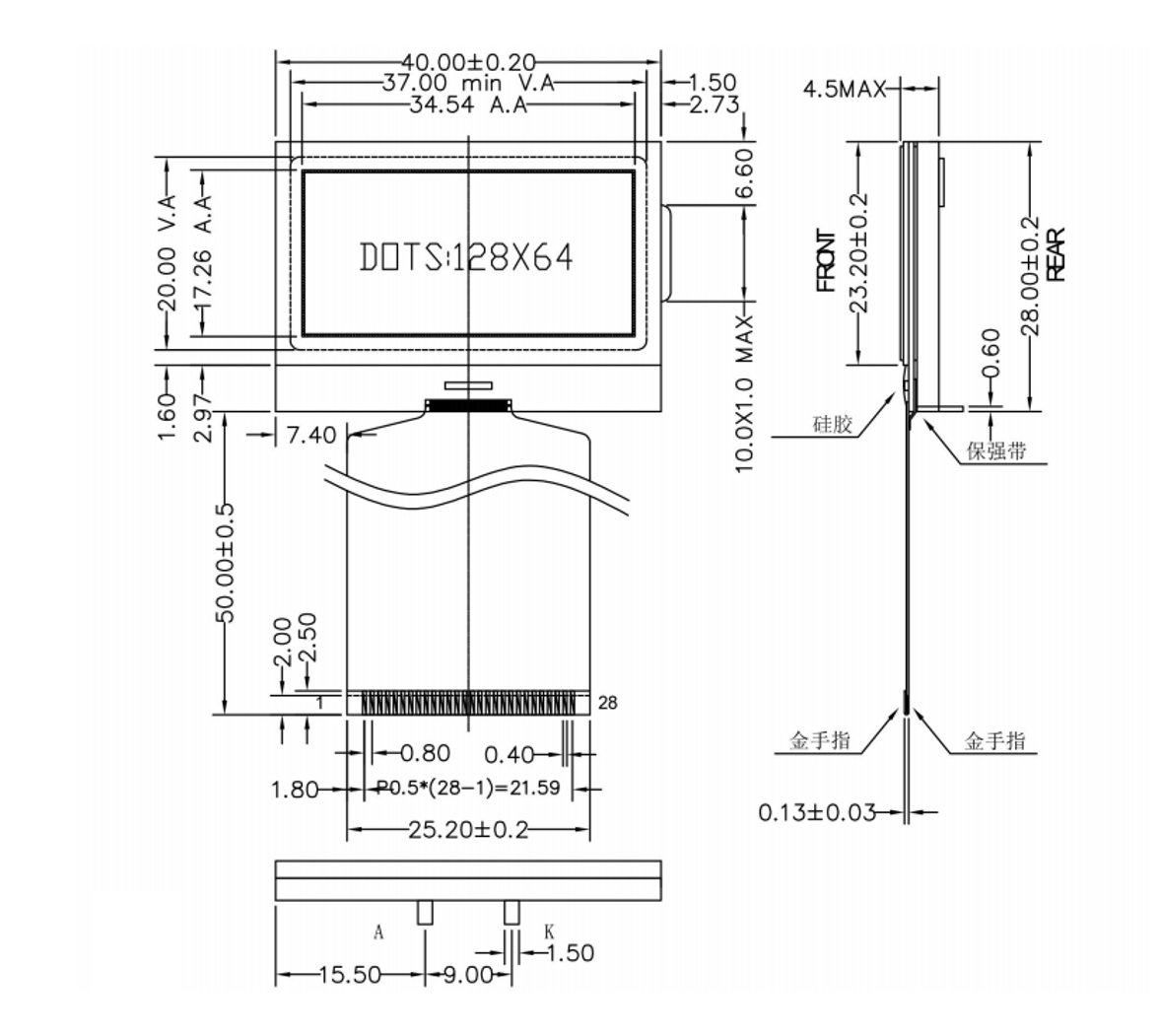
Module Size(L×W×H) | 40.0L×28.0.0W×4.5(max)H | mm |
View Area(W×H) | 37.0×20.0 | mm |
Effective Area | 128×64 | dot |
Dot Pitch(W×H) | 0.27×0.27 | mm |
Dot Size(W×H) | 0.245×0.245 | mm |
Drawing
Pin Definition
ITEM | SYMBOL | LEVEL | FUNCTION |
1 | VDD | +3.3V | Power Supply For Logic |
2 | C86 | H/L | H:6800 Parallel L:8080 Parallel |
3 | VSS | 0V | Power Ground |
4 | V0 | — | Connect a capacitor between this terminal and the VSS terminal |
5 | V1 | — | |
6 | V2 | — | |
7 | V3 | — | |
8 | V4 | — | |
9 | CAP2- | — | Connect a capacitor between this terminal and the CAP2+ terminal |
10 | CAP2+ | — | Connect a capacitor between this terminal and the CAP2- terminal |
11 | CAP1- | — | Connect a capacitor between this terminal and the CAP1- terminal |
12 | CAP1+ | Connect a capacitor between this terminal and the CAP1+ terminal | |
13 | CAP3+ | — | Connect a capacitor between this terminal and the CAP1- terminal |
14 | VOUT | Connect a capacitor between this terminal and the VSS or VDD terminal | |
15 | VSS | 0V | Power Ground |
16 ~ 23 |
D7~D0 |
H/L |
8-bit bi-directional data bus |
24 |
/RD |
H/L | 8080 Parallel:The data bus is in an output status when this signal is “L ”. 6800 Paralle:This is the enable clock input terminal of the 6800 Series MPU. |
25 |
/WR |
H/L | 8080 Parallel:The signals on the data bus are latched at the rising edge of the /WR signal. 6800 Paralle:H:Read L:Write |
26 | A0 | H/L | H:Indicates that D0 to D7 are display data. L:Indicates that D0 to D7 are control data. |
27 | /RES | H/L | The reset operation is performed by the /RES signal level |
28 | CS1 | L | Chip select signal |
MAXIMUM ABSOLUTE LIMIT
Items | Symbol | Min | Max | Unit | Condition |
Supply Voltage | Vdd | 2.5 | 3.6 | V | Vss=0V |
Input Voltage | Vin | 0 | Vdd | V | Vss=0V |
Operating Temperature | Top | -20 | +70 | ℃ | No Condensation |
Storage Temperature | Tst | -30 | +80 | ℃ | No Condensation |
BACKLIGHT CHARACTERISTICS (Color:White)
Item | Symbol | Min. | Typ. | Max. | Unit | Condition |
Forward voltage | Vf | 2.8 | 3.0 | 3.2 | V | IF=45mA Ta=25℃ |
Luminance | Lv | 280 | 350 | 420 | cd/m2 | |
Number of LED | - | - | 3 | - | Piece | - |
Connection mode | P | - | Parallel | - | - | - |
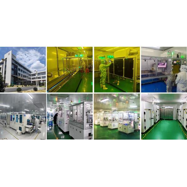
Facilities and Certification