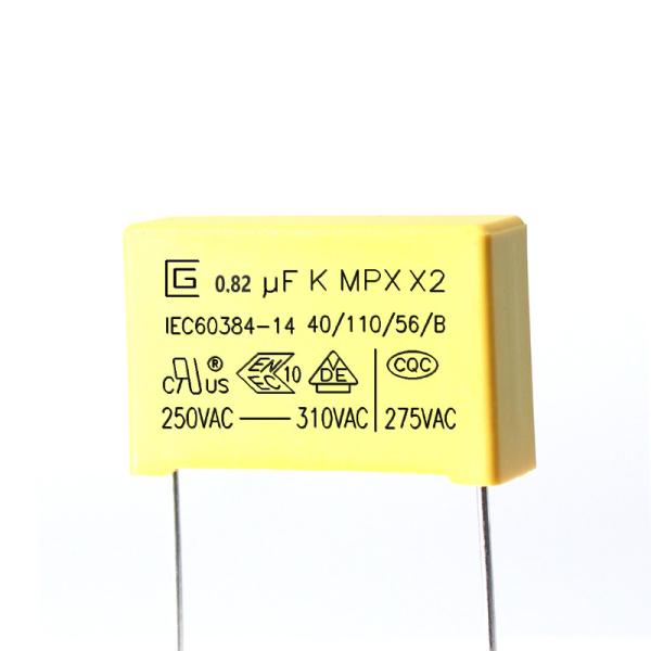
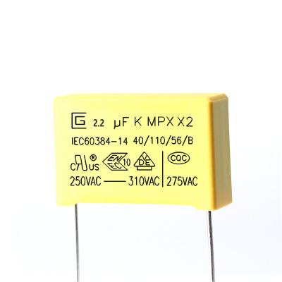
Good Stability 0.82uf 824K 275VAC X2 Safety Capacitor Good Properties In Damp Environment
X capacitor --- metallized polypropylene film capacitor; usually, X capacitor is mostly made of polyester film capacitor with relatively large ripple current resistance. This type of capacitor has a large volume, but it allows a large current for instantaneous charge and discharge, and its internal resistance is correspondingly small. The X capacitor adopts the outer square and the inner high-voltage OPP (metallized polypropylene material winding processing) in plastic packaging. The OPP material not only has better electrical performance, but also can effectively reduce the impact of high-frequency pulses when connected in parallel with the input end of the power supply. Power effects.
X2 Safety Capacitor.pdf
Characteristics of X2 Safety Capacitors
Non-inductive construction with metallized polypropylene film.
Excellent moisture resistance.
self-healing.
Excellent flame retardant properties.
Capable of withstanding overvoltage shocks.
The use of X2 safety capacitors.
Suppresses electromagnetic interference.
Jumper the lines.
It is suitable for the resistance-capacitance step-down of ammeters, LED drivers, controllers, etc. in series in the circuit.
Products Introduction
MPX are winded with metallized polypropylene film dielectric,Non-inductive construction, tinned copper wire leads,and flame retardant epoxy resin coating. They have excellent features of self-healing and good flame retardant according to UL 94-V0
Features
1.This is specifically designed for applications in serial with the 100Vac-240Vac main, i.e. capacitive divider, for example,energy meter, LED driver etc.
2.Metallized polypropylene film
3.Good self-healing properties, withstanding surge voltage stressing
4.Long stability of capacifance
5.Good properties in damp environment
6.Excellent active and passive flame resistant abilities
Construction and main materials of products
Specifications(IEC 60384-14)
Test items | Performance requirements | Conditions of test |
Capacitance | Within the tolerance specified | 1KHz, 1Vrms Max. at 25℃ |
Dissipation Factor | 0.001 (0.1%) Max. | 1KHz, 1Vrms Max. at 25℃ |
Voltage proof | Shall be no abnormality | Between terminals 4.3UR (Vdc) Test of 60sec. |
Between terminal and enclosure UR×200%+1500Vac, 60sec. | ||
Insulation resistance | CR ≤ 0.33μF IR ≥ 15,000MΩ CR >0.33μF IR ≥6,000s | 100±15Vdc, 60sec / 25℃ |
Robustness of terminations | No wire breakage and no damage of capacitor | Tense Strength of Terminal Load Force : 1.0 Kg Holding Time : 10 ± 1sec |
Bending Strength of Terminal Load Force : 0.5 Kg Bending Time : 4 x 90 ゚ | ||
Resistance to soldering heat | (1) Appearance : No visible damage (2) △C/C : ≤ ±5% of the initial value | Solder temperature: 260±5℃ Solder time: 5±0.5sec |
Solderability | 95% of the surface tinning | Solder temperature: 260±5℃ Solder time: 2±0.5sec |
Rapid change of temperature | The capacitors shall be visually examined and there shall be no visible damage. | Lower category temperature: -40℃ Upper category temperature: 110℃ Number of cycles: 5 Duration t1 = 30 min |
Vibration | The capacitors shall be visually examined and there shall be no visible damage | Frequency range: 10~55Hz Course: X,Y,Z (axis) 2h / axis ( 6h in total) Displacement amplitude: 0.75mm |
Test items | Performance requirements | Conditions of test |
Climatic sequence | (1) Appearance : No visible damage (2) △C/C : ≤ ±5% of the initial value (3) DF ( tanδ) : ≤ 0.008 of increased value (4) IR : ≥ 50% of the applicable limits (5) Voltage proof : Normal | Dry Heat Upper Temperature: 110℃ Lower Duration: 16Hrs |
Cold Temperature: -40℃ Duration: 2Hrs | ||
Damp Heat Steady State | (1) Appearance : No visible damage (2) △C/C : ≤ ±5% of the Initial value (3) DF ( tanδ) : ≤ 0.008 of increased value (4) IR : ≥ 50% of the applicable limits (5) Voltage proof : Normal | +40°C and 93% RH, 56 days |
Charge and discharge | (1) Appearance : No visible damage (2) △C/C : ≤ ±10% of the initial value (3) DF ( tanδ) : ≤ 0.008 of increased value (4) IR : ≥ 50% of the applicable limits | Test voltage : √2 x URVAC 50 Hz Charge and discharge: 0.5sec/time Repeated for 10000 cycles |
Endurance | (1) Appearance : No Visible Damage (2) △C/C : ≤ ±10% of the initial value (3) DF ( tanδ) : ≤ 0.008 of increased value (4) IR : ≥ 50% of the applicable limits | 1.25 x UR VAC 50 Hz, once every hour increase to 1,000VAC for 0.1 second, 1,000 hours at upper rated temperature |
Storage conditions
1 t should be noted that the solderability of the terminals may be deteriorted when stored barely in an atmosphere for a long preriods
2 It shouldn't be located in particularly high temperature and high humidity, it must submit to the following conditions(keeping in the original package)
Temperature: 35 MAX Relative humidity:60% MAX
3 Storage period:Losse:12 monthes max (from the manufacturing date marked on the label in package bag)
Enviroment requirement
1 Compliance with the requirement of RoHS.
2 Compliance with the requirement of REACH.
3 Without Halogen(as required).
4 Please see the attachment 2 for the test reprots of the Rohs and Reach by a third party
Quality Control
Product structure
1.Inquiry and consulting support.
2.Sample testing support.
3.View our Factory.
4. After sending, we will track the products for you once every two days, until you get the product.If you have any questions about the problem, contact with us, we will offer the solve way for you.