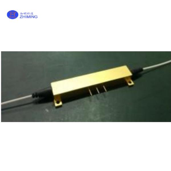
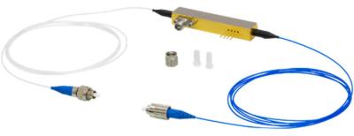
A phase modulator based on straight optical waveguides can modulate the phase of light waves through electrical signals applied to the device. For the 1000nm wavelength, we provide single-polarization optical waveguides (proton-exchanged waveguides) fabricated using annealed proton exchange (APE) technology, which exhibit a high optical power threshold and excellent polarization stability.
The 1000nm phase modulator can be categorized into low-frequency phase modulators (e.g., 100MHz) and high-frequency phase modulators (e.g., 1GHz), depending on the operating frequency.
Low-frequency phase modulators utilize a high-impedance lumped-electrode modulation structure, making them suitable for applications requiring low modulation frequencies (e.g., DC to 100MHz).
High-frequency phase modulators employ a 50Ω impedance coplanar traveling-wave electrode structure, optimized for high modulation frequencies (e.g., 1–10GHz).
The 1000nm phase modulator features low insertion loss, low driving voltage, and high stability, making it ideal for applications in fiber optic sensing, optical communications, microwave photonic links, laser coherent beam combining, and more.
Working Principle
Core Mechanism: Electro-Optic Effect
When an electrical signal is applied to the modulator’s electrodes, it creates an electric field within the proton-exchanged optical waveguide (made of materials like lithium niobate).
This electric field slightly alters the waveguide’s refractive index (a property governing light propagation speed).
As light travels through the waveguide, its phase shifts in proportion to the applied voltage and the interaction length of the electrode.
Design Variations for Frequency Ranges
Uses a lumped-electrode structure where the electrode is short and simple.
The electric field uniformly affects the entire waveguide, making it efficient for slow or static signals (e.g., DC to 100MHz).
Ideal for precision control in applications like fiber optic sensing or slow-tuning systems.
Employs a traveling-wave electrode designed like a high-speed transmission line (impedance-matched to 50Ω).
The electrical signal travels along the electrode in sync with the light wave, minimizing signal delay mismatch.
Enables ultrafast phase modulation for high-frequency applications like microwave photonics or laser radar.
Key Performance Advantages
High Power Handling: The annealed proton exchange (APE) waveguide resists optical damage even under intense laser power.
Stable Polarization: The waveguide supports only one polarization, avoiding interference from unwanted polarization shifts.
Efficiency: Low driving voltage and minimal optical loss ensure energy-efficient operation.
Applications
Fiber Optic Sensing
Optical Communications
Microwave Photonics
Laser Systems
Quantum Technologies
Biophotonics & Medical Imaging
Technical Specifications
Category | Parameter | Typical Value | Unit |
Optical Specifications | Crystal Orientation | X-cut Y-propagating lithium niobate, LiNbO₃ | - |
Waveguide Fabrication | Proton Exchange, Single Polarization | - | |
Operating Wavelength | 1000 nm ± 20 | nm | |
Insertion Loss | ≤ 4.0 | dB | |
Pigtail Polarization Extinction Ratio | ≥ 20 | dB | |
Optical Return Loss | -45 | dB | |
Electrical Specifications | Operating Frequency | DC~100M | Hz |
Half-Wave Voltage, Vπ | ≤ 3.0 | V | |
RF Impedance | 1M | Ω | |
RF Interface | SMA | - | |
Package Configuration | Input Fiber | HI1060 single-mode fiber or PM980XP polarization-maintaining (PM) fiber | - |
Output Fiber | HI1060 single-mode fiber or PM980XP polarization-maintaining (PM) fiber | - | |
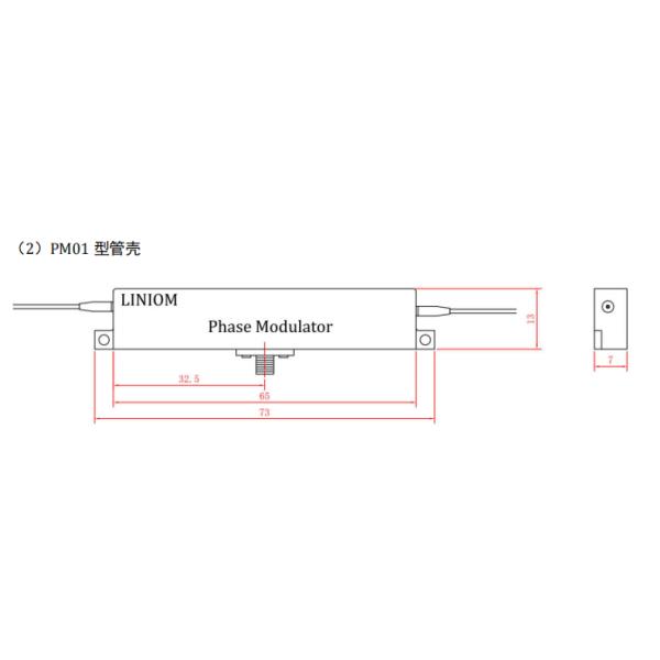
Package Housing | K5509,PM01 | - |
Category | Parameter | Typical Value | Unit | ||
Optical Specifications | Crystal Orientation | X-cut Y-propagating lithium niobate, LiNbO₃ | - | ||
Waveguide Fabrication | Proton Exchange, Single Polarization | - | |||
Operating Wavelength | 1300 nm ± 20 | nm | |||
Insertion Loss | ≤ 4.0 | dB | |||
Pigtail Polarization Extinction Ratio | ≥ 20 | dB | |||
Optical Return Loss | -45 | dB | |||
Electrical Specifications | Operating Frequency | 1.0 | 5.0 | 10.0 | GHz |
Half-Wave Voltage, Vπ | ≤ 3.5 | ≤ 4.0 | ≤ 5.0 | V | |
RF Impedance | 50 | Ω | |||
RF Interface | SMA | - | |||
Package Configuration | Input Fiber | HI1060 single-mode fiber or PM980XP polarization-maintaining (PM) fiber | - | ||
Output Fiber | HI1060 single-mode fiber or PM980XP polarization-maintaining (PM) fiber | - | |||
Package Housing | PM02 | - |
Parameter | Typical Value | Unit |
Input Optical Power | ≤ 100(Proton Exchange Waveguide) | mW |
Maximum RF Power | ≤ 20 | dBm |
Operating Temperature | 0 ~ +70 | ℃ |
Storage Temperature | -40 ~ +85 | ℃ |
Fiber Bend Radius | ≥ 50 | mm |
Custom Item | Optional Parameter | Notes |
Low Insertion Loss | ≤ 3.0 dB | |
Low Half-Wave Voltage (Vπ) | ≤ 2.5 V | Available for PM1000 series only |
Fiber Jacket | None (Bare Fiber) | |
Fiber Connector | Bare Fiber, FC/UPC, LC/PC, APC, etc. |