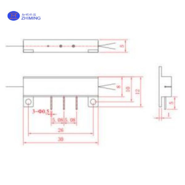
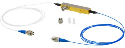
The Y-waveguide modulator is a multifunctional integrated optical device that combines various functions such as polarization initiation, wave guiding, beam splitting, beam combining, and phase modulation.
It is a core optoelectronic component in interferometric fiber sensor systems, such as fiber optic gyroscopes and fiber optic current transformers.
The Y-waveguide modulator utilizes a proton exchange process to fabricate low-loss optical waveguides with high polarization extinction ratios on lithium niobate wafers. A metal thin film is deposited on top of the waveguide to create the modulation electrode structure.
The precision-polished modulator chip is coupled and bonded to panda polarization-maintaining fiber with a small mode field size using precise fiber alignment and high-reliability fiber coupling technology.
Working Principle
Light Splitting and Combining
A Y-shaped optical waveguide splits incoming light into two paths. After passing through the waveguide arms, the light recombines.
Voltage-Driven Phase Shift
Electrodes placed near the waveguide apply a voltage. This voltage slightly alters the refractive index of the LiNbO₃ crystal, creating a phase difference between the two light paths.
Interference-Based Output
When the light recombines, the phase difference determines whether the output light brightens or dims. A specific voltage (called the half-wave voltage, Vπ) can fully switch the light from "on" to "off."
Polarization Stability
Integrated with polarization-maintaining fibers to ensure light travels in a fixed polarization state, critical for precise measurements.
Temperature Resilience
LiNbO₃’s stability allows consistent performance even in extreme temperatures (-45°C to +85°C).
Fiber Optic Gyroscopes (FOGs)
Serve as the core component in inertial navigation systems, enabling sub-milliradian angular velocity detection through precision phase modulation.
Ideal for aerospace and autonomous vehicles, with low power consumption meeting stringent energy constraints in satellites and drones.
Smart Grid Current Sensing
Enable passive high-voltage measurements in fiber optic current transformers (FOCTs), resisting electric field interference above 100 kV for real-time grid monitoring and fault detection, compliant with IEC 60044-8.
Quantum Communication and Sensing
Support GHz-rate photon-state modulation in quantum key distribution (QKD) systems, compatible with cryogenic environments (-196°C) for superconducting single-photon detectors.
High-Speed Optical Communication
Deliver DC-40 GHz RF bandwidth for 5G millimeter-wave fronthaul and microwave photonic links, coupled with low-loss (<0.5 dB) small-mode-field polarization-maintaining fiber (MFD ≈5.3 μm).
Technical Specifications
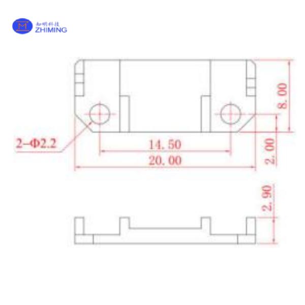
We can offer the following standard models of Y-waveguide modulator products:
Production | Wavelength | Input Fiber Diameter [µm] | Output Fiber Diameter [μm] | Fiber Type | Package Model | ||
Code | [nm] | Cladding | Coating | Cladding | Coating | No. | |
Y1301 | 1310 | 80 | 165 | 80 | 165 | Small-Mode-Field Polarization-Maintaining | C302 |
Y1303 | 1310 | 125 | 250 | 80 | 165 | Small-Mode-Field Polarization-Maintaining | K302 |
S1301 | 1310 | 80 | 165 | 80 | 165 | Small-Mode-Field Polarization-Maintaining | S202 |
S1302 | 1310 | 80 | 165 | 80 | 165 | Small-Mode-Field Polarization-Maintaining | K202 |
Y1501 | 1550 | 80 | 165 | 80 | 165 | Small-Mode-Field Polarization-Maintaining | C302 |
Category | Parameter | Typical Value | ||
Y13XX | S13XX | Y15XX | ||
Optical (Room Temperature) | Operating Wavelength | 1310nm | 1310nm | 1550nm |
Insertion Loss | ≤ 4.0 dB | |||
Splitting Ratio | 50 ± 3% | |||
Polarization Crosstalk (Pigtail Fiber) | ≤ -28 dB | |||
Optical(Full Temperature Range) | Insertion Loss Variation | ≤ 0.5 dB | ||
Splitting Ratio Variation | ≤ 5% | |||
Polarization Crosstalk (Pigtail Fiber) | ≤ -25dB | |||
Electrical | Half-Wave Voltage (Vπ) | ≤ 3.5 V | ≤ 4.5V | ≤ 4.5V |
Operating Bandwidth | ≥ 100 MHz | |||
Residual Intensity Modulation | ≤ 4‰ | |||
others | Operating Temperature | -45°C to +70°C | ||
Storage Temperature | -55°C to +85°C | |||
Alignment Method | Fast-axis Operation | |||
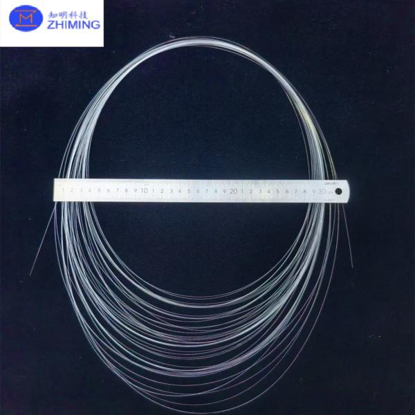
Fiber Length | ≥1.5 meters (≥1.5 m) |
Test Item | Test Condition |
High-Temperature Storage | +85°C, ≥48 hours |
Low-Temperature Storage | -55°C, ≥48 hours |
Temperature Cycling | -55°C to +85°C, ≥10 cycles |