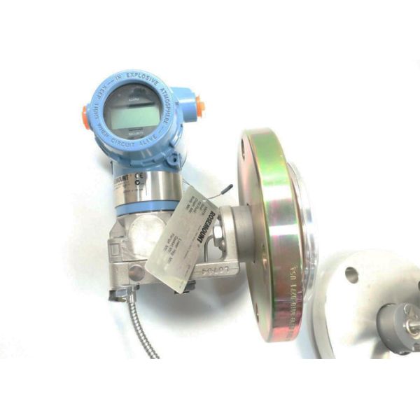
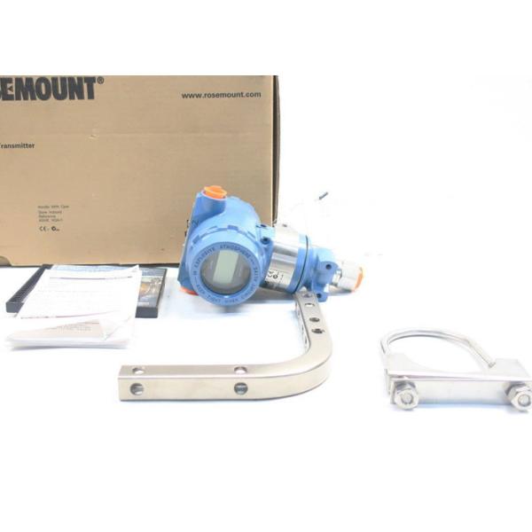
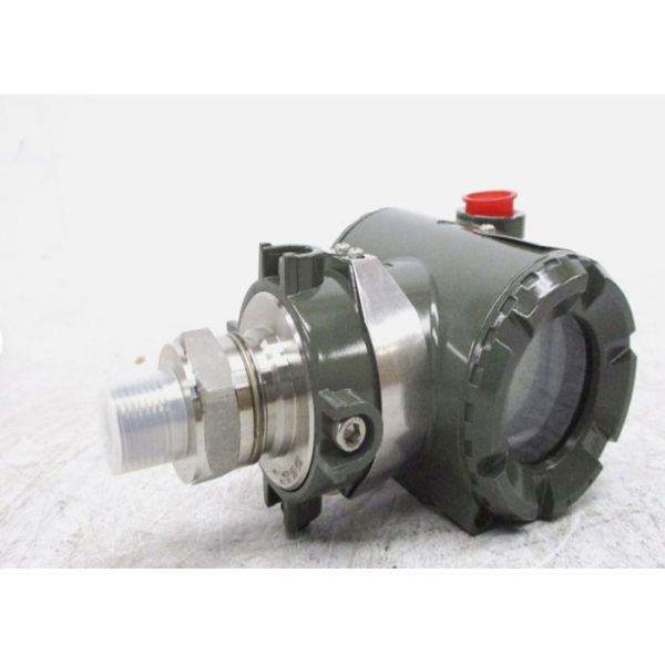
YoKogawa YTA110-EA2DK/X1/KU2 Differential Pressure Transmitter New Original
The YTA110 is the high performance temperature transmitter that accepts Thermocouple, RTD, ohms or DC milivolts inputs and converts it to a 4 to 20 mA DC signal for transmission. The YTA110 supports either BRAIN or HART communication protocol. The YTA110 in it standard configuration is certified by TU¨ V as complying with SIL2 for safety requirement.
■ FEATURES
High performance Microprocesser-based sensing technology ensures long-term accuracy and high reliability. High reliability Dual-compartment housing realizes high resistance capability to harsh environments, and YTA110 has SIL2 capability for safety requirement. Variety of sensor inputs The type of sensor input is user-selectable from thermocouples (T/C), RTDs, ohms, or DC milivolts. Digital communication BRAIN or HART® communication protocol is available. The insturment configuration can be changed by the user with using the BT200 or HART communicator. Self-diagnostics function Continuous self-diagnostics capability ensures longterm performance and lower cost of ownership. LCD display with bargraph The LCD display provides both a digital readout and percent bargraph simultaneously
■ STANDARD
SPECIFICATIONS PERFORMANCE SPECIFICATIONS Accuracy (A/D accuracy/span + D/A accuracy) or 0.1 % of calibrated span, whichever is greater. See Table 1. on page 3. Cold Junction Compensation Accuracy (For T/C only) ± 0.5˚C (± 0.9 ˚F) Ambient Temperature Effect (per 10 ˚C change) ± 0.1 % or ± (Temperature Coefficient /span), whichever is greater. See Table 2. for Temperature Coefficient. Stability RTD: 0.1% of reading or 0.1°C per 2 years, whichever is greater at 232°C
T/C: 0.1% of reading or 0.1°C per year, whichever is greater at 232°C. 5 Year Stability RTD: 0.2% of reading or 0.2°C, whichever is greater at 232°C. T/sC: 0.4% of reading or 0.4°C, whichever is greater at 232°C. RFI Effect Tested per EN 50082-2, field intensity up to 10 V/m. Power Supply Effect ±0.005 % of calibration span per volt Vibration Effect 10 to 60 Hz 0.21 mm peak displacement 60 to 2000 Hz 3G Position Effect None
■ FUNCTIONAL
SPECIFICATIONS Input Input type is selectable: Thermocouples, 2-, 3-, and 4-wire RTDs, ohms and DC milivolts. See Table 1. on page 3. Span & Range Limits See Table 1. on page 3. Input signal source resistance (for T/C, mV) 1 k or lower Input lead wire resistance (for RTD, ohm) 10 per wire or lower Output Two wire 4 to 20 mA DC. Output range: 3.68 mA to 20.8 mA BRAIN or HART ® protocol is superimposed on the 4 to 20 mA signal. Any single value from the followings can be selected as the analog output signal. Sensor 1, Terminal Temperature. Also, up to three of the above values can be displayed on LCD display or read via communication. Isolation Input/Output/GND isolated to 500 V DC
Table 2. Temperature Coefficient
Sensor Type | Temperature Coefficient |
Thermocouples E,J,K,N,T,L,U | 0.08C + 0.02% of abs.reading |
Thermocouples R,S,W3,W5 | 0.25C + 0.02% of abs.reading |
T/C B 100C Reading < 300C 300C Reading | 1C + 0.02% of abs.reading 0.5C + 0.02% of abs.reading |
RTD | 0.08C + 0.02% of abs.reading |
mV | 0.002 mV + 0.02% of abs.reading |
ohm | 0.1 Ω + 0.02% of abs.reading |
Note1: Ambient Temperature Effect per 10°C change is 0.1% or (temperature coefficient/span), whichever is greater.
Note2: The “abs.reading” on Table2 means the absolute value of the reading in °C.
Example of abs reading; When the temperature value is 250 Kelvin, abs reading is 23.15, absolute (250273.15).
Example of Ambient Temperature Effect;
Conditions;
1) Input Sensor: Pt100
2) Calibration Range: 100 to 100°C
3) Reading value: 50°C Ambient Temperature Effect per 10°C; Temperature Coefficient/Span=(0.08°C0.02/100|50°C|)/{100°C(100°C)}= 0.00045 → 0.045% Therefore, Ambient Temperature Effect is 0.1%/10°C
■ DIMENSIONS
2-inch horizontal pipe mounting
< Ordering Information >
Specify the following when ordering Model, suffix codes, and optional codes
The instrument is shipped with the settings shown in Table A. Specify the following when necessary.
1. Sensor type. For RTD and resistance input, specify the number of wire as well. (Example; Pt200 3-wire system)
2. Calibration range and unit 1) Calibration range can be specified within the measurement range shown in Table 1. on page 3. 2) Specify one range from C, K, F or R for temperature input. F and R are available when Optional code D2 is specified. It is not necessary to specify the unit of mV and ohm inputs, for these units automatically will be mV or Ω.
3. Tag Number
4. Other Items related with options /CA option allows specifying the setting Descriptor for HART protocol type at factory. Specify upto 16 characters to be entered in the Descriptor parameter.
Our company
Our brands