-
- The board is designed to operate within a specific input voltage range that is typically in line with the power supply standards of the Mark IV system. While exact values may vary depending on the specific model or application requirements, it usually accepts common industrial AC (alternating current) voltages, such as 110 - 220 VAC, with a tolerance level around ±10% or ±15%. This means it can reliably function within approximately 99 - 242 VAC for a ±10% tolerance or 93.5 - 253 VAC for a ±15% tolerance. In some cases, it might also support a DC (direct current) input voltage range, perhaps something like 24 - 48 VDC, depending on the power source availability and system configuration in the industrial facility.
- Input Current Rating:
- There is an associated input current rating that specifies the maximum amount of current the device can draw under normal operating conditions. This parameter is crucial for sizing the appropriate power supply and ensuring that the electrical circuit protecting the device can handle the load. Based on its internal circuitry complexity and power consumption, it might have an input current rating typically in the range of a few hundred milliamperes to a few amperes, say 0.5 - 3 A for typical applications. However, in systems with more power-hungry components or when multiple boards are powered simultaneously, this rating could be higher.
- Input Frequency (if applicable):
- If the board is designed for AC input, it operates with a specific input frequency, usually either 50 Hz or 60 Hz, which are the common frequencies of power grids around the world. Some advanced models might be able to handle a wider frequency range or adapt to different frequencies within certain limits to accommodate variations in power sources or specific application needs.
- Output Voltage Levels:
- The DS3800HDDL generates output voltages for different purposes, such as powering connected components or providing appropriate signal levels for communication with other devices in the control system. For digital output pins, it commonly has logic levels like 0 - 5 VDC for interfacing with digital circuits on other control boards or sensors. There could also be analog output channels with adjustable voltage ranges, perhaps from 0 - 10 VDC or 0 - 24 VDC, used for sending control signals to actuators like valve positioners or variable speed drives. The specific output voltage levels depend on the functions it needs to perform and the requirements of the connected devices.
- Output Current Capacity:
- Each output channel has a defined maximum output current that it can supply. For digital outputs, it might be able to source or sink a few tens of milliamperes, typically in the range of 10 - 50 mA. For analog output channels, the current capacity could be higher, depending on the power requirements of the connected actuators, say in the range of a few hundred milliamperes to a few amperes. This ensures that the board can provide sufficient power to drive the connected components without overloading its internal circuits.
- Power Output Capacity:
- The total power output capacity of the board is calculated by considering the sum of the power delivered through all its output channels. This gives an indication of its ability to handle the electrical load of the various devices it interfaces with in the control system. It could range from a few watts for systems with relatively simple control requirements to several tens of watts for more complex setups with multiple power-consuming components.
- Analog-to-Digital Conversion (ADC) Resolution:
- The board likely incorporates an analog-to-digital converter (ADC) to handle the analog signals received from sensors. The ADC has a specific resolution, which determines how accurately it can represent the analog input signals as digital values. Given its role in industrial control where precise measurements are often necessary, it might have a relatively high ADC resolution, perhaps 12-bit or 16-bit. A higher ADC resolution, like 16-bit, allows for more detailed and accurate conversion of analog signals, enabling the detection of small variations in parameters such as temperature, pressure, or speed within a narrow range.
- Digital-to-Analog Conversion (DAC) Resolution (if applicable):
- If the board has analog output channels and uses a digital-to-analog converter (DAC), there would be a specific DAC resolution defined. Similar to the ADC, a higher DAC resolution ensures more precise control of actuators through the analog output signals. For instance, a 12-bit or 16-bit DAC can provide finer adjustments of the output signal for controlling devices like valve positioners, resulting in more accurate control of parameters such as fuel flow or valve positions in applications like turbine control.
- Signal Sampling Rate:
- There is a specific sampling rate at which the board processes incoming signals, both analog and digital. This rate determines how frequently it takes samples of the input signals for further analysis and processing. For slower-changing signals like steady-state temperature measurements, the sampling rate might be a few hundred samples per second. However, for more dynamic signals such as those related to rapidly changing turbine speeds during startup or shutdown, the sampling rate could be several thousand samples per second. A higher sampling rate is beneficial for capturing accurate data during fast transients or when monitoring parameters that change quickly.
- Supported Protocols:
- The DS3800HDDL adheres to the communication protocols specific to the Mark IV system, which may include both proprietary GE protocols and some standard industrial protocols for seamless integration with other components. It likely supports communication with other control boards, I/O modules, and monitoring systems within the Mark IV framework. While specific details might be proprietary, it would be designed to enable efficient data exchange for functions like transmitting sensor readings, receiving control commands, and sharing status information among different parts of the control system.
- Communication Interface:
- The board is equipped with physical communication interfaces that facilitate its connection to other devices. This could include Ethernet ports (perhaps supporting standards like 10/100/1000BASE-T) for high-speed wired communication over local area networks. Serial communication ports such as RS-232 or RS-485 might also be present. RS-232 is useful for shorter distance, one-on-one device connections, while RS-485 is suitable for longer distances and can support multi-drop configurations with multiple devices connected on the same bus. The pin configurations, cabling requirements, and maximum cable lengths for reliable communication over these interfaces would be specified. For example, an RS-485 serial port might have a maximum cable length of several thousand feet under certain baud rate conditions for reliable data transmission in a large industrial facility.
- Data Transfer Rate:
- There are defined maximum data transfer rates for sending and receiving data over its communication interfaces. For Ethernet-based communication, it could support speeds up to 1 Gbps (gigabit per second) or a portion of that depending on the actual implementation and the connected network infrastructure. For serial communication, baud rates like 9600, 19200, 38400 bps (bits per second), etc., would be available options. The chosen data transfer rate would depend on factors such as the amount of data to be exchanged, the communication distance, and the response time requirements of the system.
- Operating Temperature Range:
- It has an operating temperature range within which it can function reliably, typically designed to cover the temperature variations found in industrial environments. This range might be something like -20°C to +60°C or similar, allowing it to operate effectively in settings where there can be heat generated by operating equipment or where ambient temperatures can change due to external factors like weather conditions or the layout of the facility. In some extreme industrial applications, a wider temperature range might be required, and the board could potentially be customized to meet those specific needs.
- Storage Temperature Range:
- A separate storage temperature range is defined for when the device is not in use. This range is usually wider than the operating temperature range to account for less controlled storage conditions, such as in a warehouse. It could be something like -40°C to +80°C to accommodate various storage environments.
- Humidity Range:
- The board can operate within a specific humidity range, typically around 10% - 90% relative humidity (without condensation). Humidity can affect the electrical insulation and performance of electronic components, so this range ensures proper functioning in different moisture conditions. In environments with high humidity, like in some coastal industrial plants, proper ventilation and protection against moisture ingress are important to maintain the device's performance.
- Protection Level:
- It might have an IP (Ingress Protection) rating that indicates its ability to protect against dust and water ingress. For example, an IP20 rating would mean it can prevent the ingress of solid objects larger than 12mm and is protected against water splashes from any direction. Higher IP ratings would offer more protection in harsher environments. In dusty manufacturing facilities or those with occasional water exposure, a higher IP rating might be preferred.
- Dimensions:
- While specific dimensions might vary depending on the design, it likely has a form factor that fits within standard industrial control cabinets or enclosures. Its length, width, and height would be specified to enable proper installation and integration with other components. For example, it might have a length in the range of 6 - 10 inches, a width of 4 - 6 inches, and a height of 1 - 3 inches, but these are just rough estimates.
- Weight:
- The weight of the device is also relevant for installation considerations, especially when it comes to ensuring proper mounting and support to handle its mass. A heavier control board might require sturdier mounting hardware and careful installation to prevent damage or misalignment.
- EPROM Capacity:
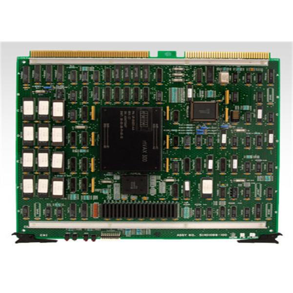
- The fifteen Electrically Erasable Programmable Read-Only Memories (EPROMs) on the board, along with the spare EPROM location, have a specific combined storage capacity. This capacity is used to store essential data such as configuration settings, calibration parameters, and firmware-related information. The capacity could range from a few kilobytes to several megabytes, depending on the specific requirements and design of the board, allowing for the storage of different types of data needed for its operation and any potential customizations.
|