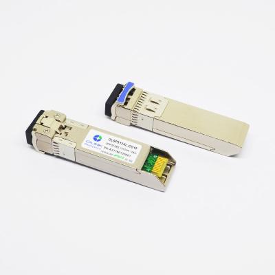
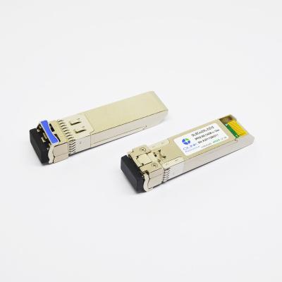
Brocade Compatible SR 25G SFP28 Transceiver 100m Multi Mode Fiber
25G SFP28 850nm 100m LC MMF Compatible Brocade SFP28-SR Transceiver
Descriptions
The 25G SFP28 850nm 100m LC MMF compatible Brocade SFP28-SR transceiver is designed for use in 25Gb/s data rateover Multi-mode fiber for link length 100m.
The transceiver designs are optimized for high perform-ance and cost effective to supply customers the best solutions for 25Gb/s single lane optical links.
Absolute Maximum Ratings
Parameter | Symbol | Min. | Max. | Unit | Note |
Supply Voltage | Vcc | -0.5 | 4.0 | V | |
Storage Temperature | TS | -40 | 85 | °C | |
Relative Humidity | RH | 0 | 85 | % |
Note: Stress in excess of the maximum absolute ratings can cause permanent damage to the transceiver.
General Operating Characteristics
Parameter | Symbol | Min. | Typ | Max. | Unit | Note |
Data Rate | 25.78 | Gb/s | ||||
Supply Voltage | Vcc | 3.13 | 3.3 | 3.47 | V | |
Supply Current | Icc | 300 | mA | |||
Operating Case Temp. | Tc | 0 | 70 | °C |
Electrical Characteristics (TOP(C) = 0 to 70 ℃, VCC = 3.13 to 3.47 V)
Parameter | Symbol | Min. | Typ | Max. | Unit | Note | ||
Transmitter | ||||||||
Differential data input swing | VINPP | 120 | 800 | mVpp | 1 | |||
Tx Disable input | H | TDH | 2.0 | Vcc+0.3 | V | |||
L | TDL | 0 | 0.8 | |||||
Tx Fault output | H | TFH | 2.0 | Vcc+0.3 | V | 2 | ||
L | TFL | 0 | 0.8 | |||||
Input differential impedance | Rin | 100 | Ω | |||||
Receiver | ||||||||
Differential data output swing | Vout,pp | 340 | 650 | 800 | mVpp | 3 | ||
Rx Los Output | H | VOH | 2.0 | Vcc+0.3 | V | 2 | ||
L | VOL | 0 | 0.8 |
Note:
1. TD+/- are internally AC coupled with 100Ω differential termination inside the module.
2. Tx Fault and Rx LOS are open collector outputs, which should be pulled up with 4.7k to 10kΩ resistors on the host board. Pull up voltage between 2.0V and Vcc+0.3V.
3. RD+/- outputs are internally AC coupled, and should be terminated with 100Ω (differential) at the user SERDES.
Optical Characteristics (TOP(C) = 0 to 70 ℃, VCC = 3.13 to 3.47 V)
Parameter | Symbol | Min. | Typ | Max. | Unit | Note |
Transmitter | ||||||
Operating Wavelength | λ | 840 | 850 | 860 | nm | |
Ave. output power (Enabled) | PAVE | -8.2 | 2.4 | dBm | ||
Side-Mode Suppression Ratio | SMSR | 30 | dB | |||
Extinction Ratio | ER | 2 | dB | |||
RMS spectral width(-20dB) | Δλ | 1 | nm | |||
Relative Intensity Noise | RIN | -130 | dB/Hz | |||
Receiver | ||||||
Operating Wavelength | 840 | 850 | 860 | nm | ||
Stressed Receiver Sensitivity(OMA) | RsenS | -5.2 | dBm | |||
Average Receiver Power | Pimax | -10.3 | 3 | dBm | 1 | |
LOS Assert | Pa | -30 | dBm | |||
LOS De-assert | Pd | -12 | dBm | |||
LOS Hysteresis | Pd-Pa | 0.5 | 5 | dB |
Notes:
1. Measured at the BER less than 5E-5, back to back. The measure pattern is PRBS 231-1 with worst ER=4.5@ 25.78Gb/s.