65dB/17dBm GSM 900MHz Signal Booster Good Helper of Repeaters(GW-17G-V)
Reduces dropped and missed calls. Improves data speeds.
Covers 500 sqm. of a home/ office, depending on option chosen.
Supports multiple devices and users simultaneously.
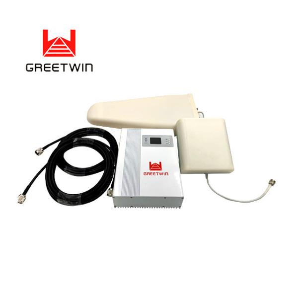
with cutting-edge technology, reducing dropped and missed calls and extending battery life for multiple simultaneous users on all cellular networks. The Omni & Whip antenna cellular signal booster kit is very cheap thanks to our clearance sale! These're definitely not refurbished signal boosters.
They are brand new cell phone boosters made by GreetWin.
Signal Booster Introduction:
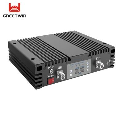
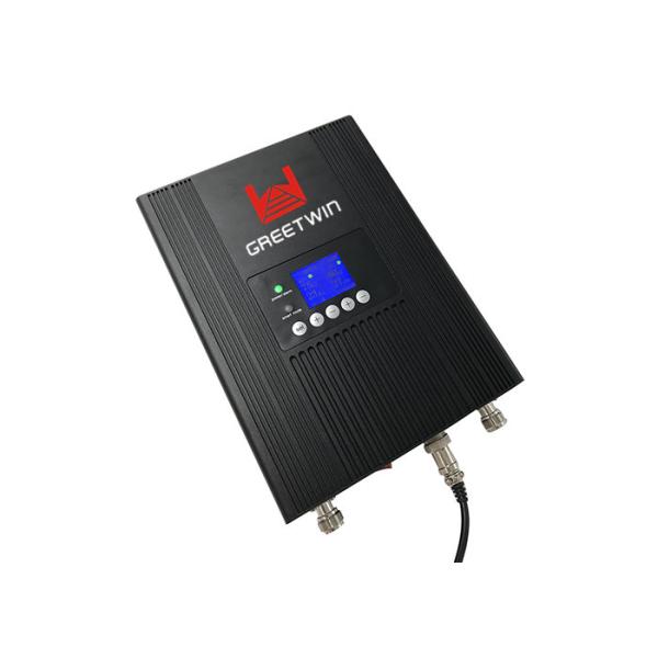
Signal Booster GW-17G-V is designed to enhance and improve the quality of mobile 2G GSM900 connection. There’re black and white colors for options. The Led Indicator will show the current level of the input signal, which simplifies the installation of the external antenna. High quality aluminum shell provides an optimal cooling. This model, as simple in connection, installation and configuration, does not require special skills.
Signal Booster Specification:
Frequency Range | Uplink | Downlink | |
GSM 900MHz | 890 - 915MHz | 935 - 960MHz | |
Max. Gain | 60dB | 65dB | |
Max. Output Power | 15dBm | 17dBm | |
Band width | Wide Band | ||
Manual Gain Control | 12dB / 1dB Step | ||
Automatic Gain Control | >30dB | ||
Ripple in Band | 6dB; | ||
Noise Figure | ≤ 6dB | ||
VSWR | ≤ 2.0 | ||
Intermodulation Products | 9KHz~1GHz | ≤ -36dBm | |
1~12.75GHz | ≤ -30dBm | ||
Spurious Emission | 9KHz~1GHz | ≤ -36dBm | |
1~12.75GHz | ≤ -30dBm |
Time Delay | ≤ 1.5 μs | ||
Frequency stability | ≤ 0.01ppm | ||
MTBF | > 50000 hours | ||
Impedance | 50 ohm | ||
Power Supply | AC 90-264V,DC 6V/3A | ||
Power LED | Power indicator | ||
ISO(Alarm LED) | Red | Self oscillation or Strong input signal, ALC>25dB, auto shut down. | |
Green | Normal | ||
Mechanical Specification | |||
RF Connector | N-Female | ||
Switch | Power Switch | ||
Cooling | Heatsink Convection cooling | ||
Humidity | < 90% | ||
Operating Temperature | -20°C ~ +55°C | ||
Environment Conditions | IP40 | ||
Installation Type | Wall Installation | ||
Size | 118mm×90mm×18mm | ||
Weight | < 0.8Kg |
Signal Booster Instruction:
About POWER, Signal Bar, ISO, UL, DL indicators.
POWER LED | Green | Normal |
Off | DC power problem | |
Signal Bar | Off | Output power too small |
Signal Bar | Green | Normal working |
Red | Working at Maximum output power | |
UL | Manual gain control of Uplink, 1=4dB, 2=8dB Decrease 4dB, put down 1 Decrease 8dB, putdown 2 Decrease 12dB, putdown 1+2 together | |
DL | Manual gain control of Uplink, 1=4dB, 2=8dB Decrease 4dB, put down 1 Decrease 8dB, putdown 2 Decrease 12dB, putdown 1+2 together | |
ISO(ALARM LED) | Green | It is working in linearity. |
Red | There are strong input signals or severe self oscillation. Please adjust the gain to see if it's too strong input signals; After that, if it's still red, that means much closer distance between indoor and outdoor antenna, please put them in longer distance between antennas. | |
MGC | UL | Uplink Gain Control |
DL | Downlink Gain Control |
FAQ:
1. After installing booster signal not be very good, indoor signal coverage very small ?
> Adjust outdoor antenna's location and direction
> Change another high gain outdoor antenna
> Check whether cables are connected well
> Change more powerful repeater
2. Cell phone signal full bar, but communication quality bad ?
> Much closer distance between indoor and outdor antenna, separate them with a longer distance.
3. After installing booster not only signal be good, but also more bad ?
> Much closer distance between indoor and outdor antenna, separate them with a longer distance.
4. Working good for long time, suddenly signal bad ?
> Check whether outdoor cable connectors are flooded
> Check whether power light is working normally
> If cables are not flooded and power light is working normally, the booster should has problems and need to be sent back to factory for repair.
Signal Booster Installation:
The booster is fixed onto the wall through expansion bolts.
A. Drill holes on the targeted place and install expansion bolts.
B. Align the holes with the expansion bolts, place flat washers, spring washers, and nuts in turn, and tighten the nuts to fasten the installing support.
C. Place the booster on and fasten it.
D. Connect cables and power cables to the booster respectively.
E. After installing the booster as described above, power on the booster to check the operation status.
Signal Booster Connection:
A. BTS Port: donor antenna cable is connected with Outdoor Port;
B. MS Port: service whip antenna is connected with Indoor Port;
C. DC IN: connected with Power adaptor.