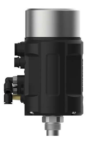
1. Product Description
1600 Series compact positioner is optimized for integrated mounting on the pneumatic actuators in the process valve and is specially designed for the requirements of a hygienic process environment. The control air channel is integrated in the actuator without external tubings. The easy handling and the selection of additional software functions are done either on a big graphic display with keypad. The control of single or double-acting actuators is done without internal air consumption. The housing is easy to clean and features proven IP protection and chemically resistant materials for use in hygienic processing, in food & beverage and pharmaceutical industries.
2.Technical Datas
Material | PC,PA6-GF30,Stainless Steel,SI |
Power supply | 24V DC ±10% |
Set-point signal | 0/4-20mA or 0-5/10 V |
Input resistance for set-point signal | 240Ω at 0/4-20mA, 21KΩ at 0-5/10V |
Control medium Dust concentration Particle density Pressure condensation point Oil concentration | Neutral gases, air DIN ISO 8573-1 Class 5 (<40μm particle size) Class 5 (<10mg/m3) Cass 3 (<-20°C) Class 5 (<25mg/m3) |
Ambient Temperature | 0-70°C |
Pneumatic Connection | Plug-in hose connector G1/4(internal Φ6mm) |
Electrical Connection | M12 3-pins B-coded(cable ø 4-6mm) M12 4-pins D-coded(cable ø 4-6mm) M12 5-pins A-coded(cable ø 4-6mm) |
Supply Pressure | 3~7 bar, specific values depending on the actuator |
Air Flow Rate | 17 L/min, 58 L/min(only single-acting) |
Stroke Control Range | Linear 5-50mm Rotary 90° |
Installation | As required, Preferably with actuator in upright position, Screw. |
Protection Class | IP65 |
Power Consumption | <5W |
Explosion Proof | Ex nA IIC T4 |
3. Product type selection
4. Inferface angle adjustment
The angle can be adjusted between the positioner and the valve. If need to adjust the interface angle, relaxing the hexagon screw in place A first. Then adjusting the angle clockwise or counter-clockwise in 180°range. After adjusting the angle, locking the angle by the hexagon screw.
5. Electrical connections and pneumatic connections
X1 | ||
---|---|---|
Pin | Description | Signal type |
1 | Analogue signal output + | 0/4 – 20 mA or 0 – 5/10 V |
2 | Binary signal output 1 | 0/24 V |
3 | Binary signal output 2 | 0/24 V |
4 | Binary signal input + | 0-3V =“0”, 15-30V =“1” |
5 | Signal common GND | GND |
X2(Optional for process control only) | ||
---|---|---|
Pin | Description | Signal type |
1 | Transmitter input + | +24 V |
2 | Transmitter signal output | 4 - 20mA |
3 | Transmitter GND | GND |
X3 | ||
---|---|---|
Pin | Description | Signal type |
1 | Power supply + | +24 V |
2 | Power supply GND | GND |
3 | Set signal input + | 0/4 – 20 mA or 0 – 5/10 V |
4 | Set signal input GND | GND |
P | Air supply enter (built-in filter, filter size 5 μm) |
R | Air exhaust |
C | Check valve |
A1 | Pilot air outlet 1 |
A2 | Pilot air outlet 2 |
6. Additional software functions