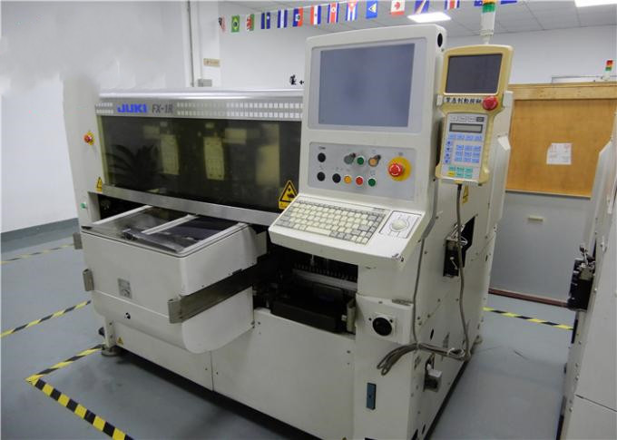
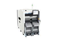
High Speed Technology JUKI KE3010 FX-3 JUKI Placement Machine convenient for users to operate and meet customer needs:
Product Advantages:
An SMT component is usually smaller than its through-hole counterpart because it has either smaller leads or no leads at all. It may have short pins or leads of various styles, flat contacts, a matrix of solder balls (BGAs), or terminations on the body of the component.
The main advantages of SMT over the older through-hole technique are:
1. Smaller components.
2. Much higher component density (components per unit area) and many more connections per component.
3. Components can be placed on both sides of the circuit board.
4. Higher density of connections because holes do not block routing space on inner layers, nor on back-side layers if components are mounted on only one side of the PCB.
JUKI placement machine has the advantages of high speed technology, convenient for users to operate and meet customer needs.
Take JUKI FX-3 as an example:
Description
JUKI FX-3 stands for ultra-fast, precise placement of micro-components on printed circuit boards. It is the perfect solution for companies wanting to process large volumes. Among the strong points of the FX-3 are short retooling times thanks to quick-change feeder banks as well as minimal maintenance. The user-friendly touchscreen interface plus the powerful optimisation software provide additional ease of use.
Features
(1) High Productivity.
The FX-3 achieves a mounting performance of up to 90,000 CPH (optimum) thanks to four independent cross-rails, each with a six-nozzle placement head set on two mounting stations, providing the machine with 24 vacuum nozzles in total.
(2) Compatible Feeders.
The FX-3 supports mechanical and electronic feeders that can be used optionally with feeder trolleys if required. This provides companies with the flexibility to keep using their existing equipment for the long term.
(3) User Friendliness.
The FX-3 includes a user-friendly operator interface with a 15-inch LCD touchscreen both at the front and the back of the machine for easy, intuitive use. This allows users to create pick-and-place programs even without extensive technical knowledge.
Specifications
Substrate size | M substrate | 410×360mm |
XL substrate | 610×560mm | |
L wide | 510×360mm | |
Component height | standard | 6mm |
Component size | Laser recognition | 0402 (British 01005) chip~33.5mm |
Element mounting speed | optimum condition | 0.040sec/chip (90,000CPH)*2 |
IPC9850 | 66,000CPH*2 | |
Laser recognition | ±0.05mm (±3σ) | |
Component mounting accuracy | Up to 120 kinds of component placement (converted to 8mm) * 5 | |
Dimension | L | 2650*1650*1530mm |
L-wide | 2880*1650*1530mm |
SMT Application
1. Manufacturing Department Production Workshop SMT Line.
2. Proper operation of the fully automatic press ensures that the machine is operating properly, thus ensuring product quality.
3. Solder Paste Printing Machine: Modern solder paste printing machine is generally composed of plates, tin paste, embossing, and transmission board. Its working principle is: firstly, the circuit board to be printed is fixed on the printing positioning table, and then the solder paste or the red glue is printed on the corresponding pad through the steel mesh by the front and rear scrapers of the printing machine, and the PCB which is uniformly printed is passed through. The transfer station is input to the placement machine for automatic placement.