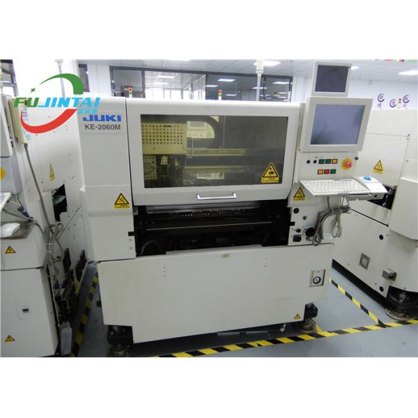
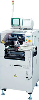
High Speed Modular SMT Mounter Machine KE-3010 Durable With Good Condition
Descriptions:
The KE-3010 is JUKI's latest leading-edge technology for improved flexibility and production quality. It supports both electronic and mechanical tape feeders and can handle boards up to 610x560 mm. With its multi-nozzle (six nozzles) laser head, the KE-3010 can achieve a rated IPC9850 speed of 18,500 cph and is capable of a component placement range from 01005 to 33x33 mm.
Features:
♦ Single Gantry, 1 Head per Gantry:
Ideal for high-mix, high-changeover, environments...
♦ 6 Nozzles per Gantry (plus IC Head on 3020V):
It can place 6 components simultaneously and center on the fly...
♦ High Accuracy Low Noise Ball Screw Drive With Linear Encoders:
♦ High Accuracy Laser Align Component Centering:
Select centering method based on component type, ship, size and material...
♦ High Speed Strobing Vision Centering System (3020V only):
On-the-flying-vision centering increase placement speed by eliminating wasted stops over camera...
♦ Quick Change Feeder Trolleys:
Supports both electronic and mechanical feeder trolleys...
♦ Standard POP Capacibility:
Package-on-package assembly is fully supported using either linear or rotary fluxer units...
Specifications:
JUKI KE-3010 | |
Board Size | M size (330x250 mm) |
L size (410×360 mm) | |
L-wide size (510×360 mm)* 1 | |
XL size (610×560 mm) | |
Applicability to long PWB (M size)* 2650x250mm | |
Applicability to long PWB (L size)* 2 800×360mm | |
Applicability to long PWB (L-wide size)* 2 1,010×360mm | |
Applicability to long PWB (XL size)* 2 1,210×560mm | |
Component height | 6mm |
12mm | |
Component size | Laser recognition |
0402(01005)~33.5mm | |
Image recognition (MNVC option) |
Standard camera: 3mm* 3~33.5mm |
Precision camera | 1.0×0.5mm* 4~20mm |
Placement speed | Condition: 0.153 sec/ chip, 23500CPH |
MNVC IC (condition): 9000CPH (optional) | |
Placement accuracy | Laser recognition: ±0.05 mm (±3σ) |
Vision recognition: ±0.04 mm | |
Feeder Inputs | Max.160 in case of 8mm tape (on a Electric double tape feeder)*7 |
Device Size (W*D*H) |
M substrate: 1500x1580x1500mm |
L substrate: 1500x1690x1500mm | |
L-Wide substrate: 1800x1690x1500mm | |
E substrate with: 2131x1890x1500mm | |
Device Weight | M-type substrate about 1850kg |
L-type substrate about 1950kg | |
XL type substrate about 2250kg |
Advantages:
An SMT component is usually smaller than its through-hole counterpart because it has either smaller leads or no leads at all. It may have short pins or leads of various styles, flat contacts, a matrix of solder balls (BGAs), or terminations on the body of the component.
The main advantages of SMT over the older through-hole technique are:
♦ Smaller components.
♦ Much higher component density (components per unit area) and many more connections per component.
♦ Components can be placed on both sides of the circuit board.
♦ Higher density of connections because holes do not block routing space on inner layers, nor on back-side layers if components are mounted on only one side of the PCB.