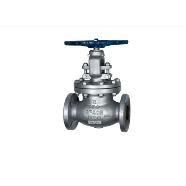
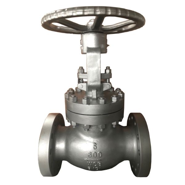
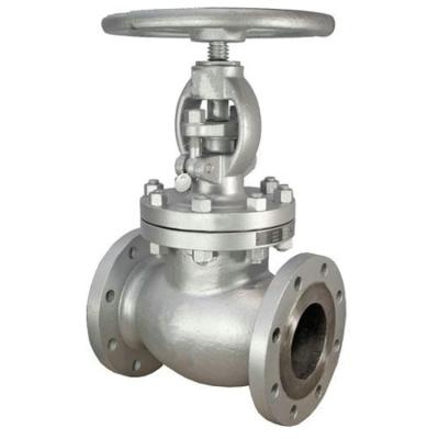
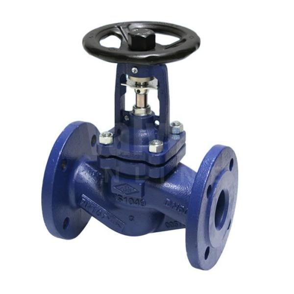
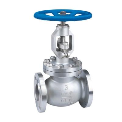
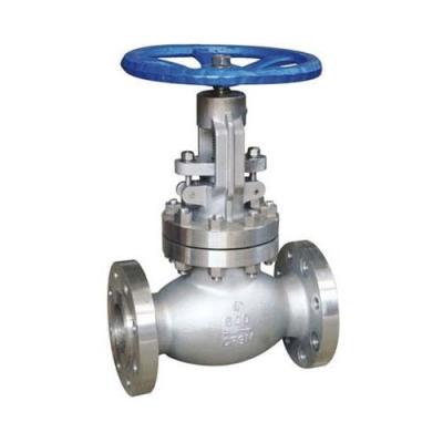
Stainless Steel Globe Valve Flanged Globe Valve DN25 DN300 Flange Self Sealing Easy To Maintain
The stainless steel globe valve is a compulsory sealed valve, so when the valve is closed, pressure must be applied to the disc to force the sealing surface to not leak. When the medium enters the valve from below the valve disc, the resistance to be overcome by the operating force is the friction between the valve stem and the packing and the thrust generated by the pressure of the medium. The force to close the valve is greater than the force to open the valve. The diameter must be large, otherwise the failure of the valve stem bending will occur. In recent years, since the emergence of self-sealing valves, the medium flow direction of the shut-off valve has changed from the upper part of the valve disc into the valve cavity. At this time, under the action of the medium pressure, the force to close the valve is small, and the force to open the valve is large. The diameter can be reduced accordingly. At the same time, this type of valve is also tight under the action of the medium.
Structural characteristics of stainless steel globe valve:
1. Advanced structure, reliable seal, excellent performance and beautiful appearance. The rigidity of the valve stem is increased, the noise and vibration are significantly reduced, and the service life and performance of the valve are improved.
2. The stop valve can be installed in any position of the pipeline, and the medium flows from the bottom to the top.
3. Above DN250 adopts advanced multiple seals, double brackets, guided movement (which can greatly improve the resistance to water hammer), and the medium enters from above. The stuffing room runs out, which effectively improves the valve's various performance and application range. ("Close" torque is 10% of the ordinary valve "Open" torque is 3% of the ordinary valve).
4. The stainless steel globe valve is suitable for pipes of various corrosive media, and has good corrosion resistance and sufficient strength.
5. Alloy steel globe valve is suitable for high temperature resistant steam and oil pipelines, and has high temperature resistant characteristics.
Notes When Use
1 . It should ensure that the pipe is blown clean before installation.
2 . When installing, make sure that the flow direction indicated by the arrow on the valve body should be consistent with the flow direction of the fluid.
3 . This valve has been degreased. Store and keep clean when installing.
4 . After the pipeline construction is completed, all the valves on the pipeline should be opened, and the residue in the pipeline should be thoroughly and thoroughly kept to ensure that the pipeline system is clean and free of debris.
5 . The installation system diagram with the oil-free requirements should be degreased.
6 . Slowly open and close during use.
7 . If the precision parts such as the valve disc, valve seat and valve stem are worn or damaged, it must be repaired and replaced in time.
8 . For parts such as gaskets and sealing materials, replace them with new ones each time.
Product Description
Valve Type:stainless steel globe valve |
Connection Type: flange |
Size:DN25~DN300 |
Nominal Pressure:1.6MPa,2.5MPa,4MPa,6.4MPa |
Material: Valve Body/Bonnet:CF8; Valve Stem:304; Screw Nut:aluminum bronze; |
Suitable Medium:water,steam,oil,etc |
Suitable Temparature:≤150℃ |
Design and Manufacture:Conform to GB/T 12235 |
Face-to-face:conform to GB/T 12221 |
Flange connection:conform to JB/T 179.1 |
Testing:Conform to GB/T 26480 |
PN | DN | Size(mm) | ||||||
L | D | D1 | D2 | B | N-φ | H | ||
1.6MPa | 25 | 160 | 115 | 85 | 65 | 14 | 4-14 | 275 |
32 | 180 | 135 | 100 | 78 | 16 | 4-18 | 280 | |
40 | 200 | 145 | 110 | 85 | 16 | 4-18 | 330 | |
50 | 230 | 160 | 125 | 100 | 16 | 4-18 | 350 | |
65 | 290 | 180 | 145 | 120 | 18 | 4-18 | 370 | |
80 | 310 | 195 | 160 | 135 | 20 | 8-18 | 400 | |
100 | 350 | 215 | 180 | 155 | 20 | 8-18 | 415 | |
125 | 400 | 245 | 210 | 185 | 22 | 8-18 | 460 | |
150 | 480 | 280 | 240 | 210 | 24 | 8-23 | 510 | |
200 | 550 | 335 | 295 | 265 | 26 | 12-23 | 710 | |
250 | 650 | 405 | 355 | 320 | 30 | 12-25 | 786 | |
300 | 750 | 460 | 410 | 375 | 30 | 12-25 | 925 |
Parts Name | Material | |||
CS/Trim 1 | CS/Trim 8 | CS/Trim 5 | ||
1 | Body | WCB+13CR | WCB+STL | WCB+STL |
2 | Disc | WCB+13CR | WCB+13CR | WCB+STL |
3 | Stem | ASTM A182 F6a | ||
4 | Nut | A194 2H | ||
5 | Bolt | A193 B7 | ||
6 | Gasket | SS Spiral Wound W/graphite, or SS Spiral Wound W/ PTFE, or Reinforced PTFE | ||
7 | Bonnet | A216-WCB | A216-WCB | A216-WCB |
8 | Packing | Braided Graphite or Reformed Graphite Ring or PTFE | ||
9 | Gland | ASTM A182 F6a | ||
10 | Gland Flange | A216-WCB | ||
11 | Stem Nut | Copper Alloy or A439 D2 | ||
12 | Hand Wheel | Ductile Iron or Carbon Steel |