INVERTED PRESSURE BALANCE LUBRICATED PLUG VALVE
Bolt cover,structure of flip-chip balanceable pressure and light on/off operation.An oil grove is set between valve body and seal surface,which may infuse the seal grease to increase the seal capability. Standards compliance Design and Manufacture: API 599,API 6D Face to face(end to end): API B 16.10 Flanged connection: ANSI B16.5 Butt welded end: ANSI B16.25 Test and inspection: API 598,API 6D Main pants materials NO. | Part name | Material | A216 WCB | A351 CF8 | A351 CF8M | A351 CF3 | A351 CF3M | 1~2 | Body/Nut | A193 B7/A194 2H | A193 B8/A194 8 | A193 B8M | A194 8M | 3 | Cover | A216 WCB | A351 CF8 | A351 CF8M | 4 | Gasket | Flexible graphite+stainless steel/PTFE | 5 | Plug | A182 F304 | A351 CF8 | A351 CF8M | A351 CF3 | A351 CF3M | 6 | Body | A216 WCB | A351 CF8 | A341 CF8M | A182 F304L | A351 CF3M | 7 | stem | A182 F410 | A182 F304 | A182 F316 | A182 F304L | A351 CF3M | 8 | "O" ring | NBR/FEP/SBR | 9 | Packing | Flexible graphite/PTFE | 10 | Gland | A216 WCB | A351 CF8 | A351 CF8M | 11~12 | Oichozzle/check valve | Material see body | 13 | Wrench | ASTM A47-32510 A216 WCB | INVERTED PRESSURE BALANCE LUBRICATED PLUG VALVE Dimensions | Class 150Lb | Size | inch | 1/2 | 3/4 | 1 | 1-1/4 | 1-1/2 | 2 | 2-1/2 | 3 | 4 | 5 | 6 | 8 | 10 | 12 | 14 | L-RF | mm | 108 | 117 | 127 | 140 | 165 | 178 | 190 | 203 | 229 | 254 | 267 | 292 | 330 | 356 | 381 | H | mm | 180 | 180 | 185 | 200 | 210 | 215 | 250 | 270 | 300 | 340 | 365 | 400 | 450 | 510 | 590 | W | mm | 400 | 400 | 500 | 500 | 600 | 600 | 820 | 820 | 300 | 300 | 320 | 320 | 350 | 380 | 380 | Weight | Kg | 10 | 12 | 14 | 17 | 19 | 21 | 29 | 33 | 48 | 75 | 98 | 125 | 171 | 230 | 370 | Dimensions | Class 300Lb | Size | inch | 1/2 | 3/4 | 1 | 1-1/4 | 1-1/2 | 2 | 2-1/2 | 3 | 4 | 5 | 6 | 8 | 10 | 12 | 14 | L-RF,BW | mm | 140 | 152 | 165 | 178 | 190 | 216 | 241 | 283 | 305 | 381 | 403 | 419 | 457 | 502 | 762 | H | mm | 180 | 180 | 185 | 200 | 210 | 215 | 250 | 270 | 300 | 340 | 365 | 400 | 450 | 510 | 590 | W | mm | 400 | 400 | 500 | 500 | 600 | 600 | 820 | 820 | 300 | 300 | 320 | 320 | 350 | 380 | 380 | Weight | Kg | 12 | 14 | 16 | 19 | 21 | 24 | 31 | 36 | 61 | 86 | 130 | 190 | 225 | 380 | 560 | Dimensions | Class 600Lb | Size | inch | 1/2 | 3/4 | 1 | 1-1/4 | 1-1/2 | 2 | 2-1/2 | 3 | 4 | 5 | 6 | 8 | 10 | 12 | 14 | L-RF,BW | mm | 165 | 190 | 216 | 229 | 241 | 292 | 330 | 356 | 432 | 508 | 559 | 660 | 787 | 838 | 889 | H | mm | 180 | 180 | 185 | 200 | 210 | 215 | 250 | 270 | 300 | 340 | 365 | 400 | 450 | 510 | 590 | W | mm | 400 | 400 | 500 | 500 | 600 | 600 | 820 | 820 | 300 | 300 | 320 | 320 | 350 | 380 | 380 | Weight | Kg | 14 | 16 | 18 | 20 | 24 | 29 | 35 | 47 | 91 | 129 | 210 | 320 | 660 | 920 | 1250 | Dimensions | Class 900Lb | Size | inch | 1/2 | 3/4 | 1 | 1-1/4 | 1-1/2 | 2 | 2-1/2 | 3 | 4 | 5 | 6 | 8 | 10 | 12 | 14 | L-RF,BW | mm | 229 | 229 | 254 | 279 | 305 | 368 | 419 | 381 | 457 | 559 | 610 | 737 | 838 | 965 | 1029 | H | mm | 180 | 180 | 185 | 200 | 210 | 215 | 250 | 270 | 300 | 340 | 365 | 400 | 450 | 510 | 590 | W | mm | 400 | 400 | 500 | 500 | 600 | 600 | 820 | 820 | 300 | 300 | 320 | 320 | 350 | 380 | 380 | Weight | Kg | 17 | 19 | 21 | 24 | 30 | 37 | 44 | 65 | 110 | 160 | 255 | 380 | 810 | 1050 | 1460 | |
Needle Valve Work:
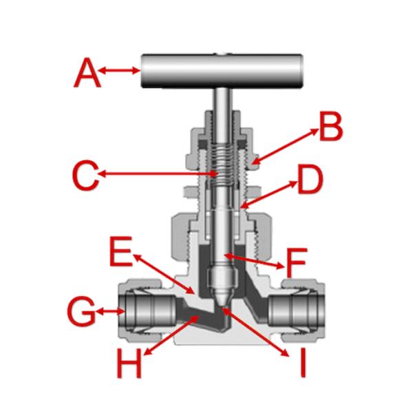
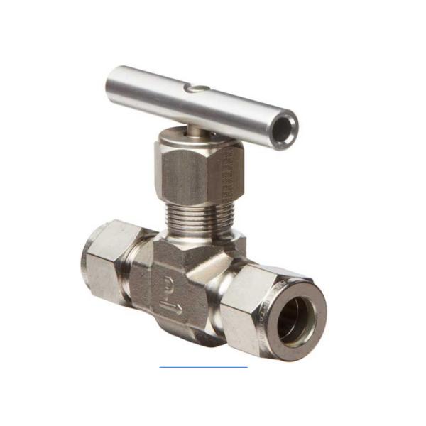
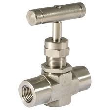
Needle valves open and close an orifice with a tapered end that raises and lowers with the spin of a handle. Figure 2 shows a needle valve cross sectional view, design, and components. The handle (A) is connected to the plunger, also called a stem (F). When you turn the handle, the plunger moves up or down based on the threads (C). The locking nut (B) prevents it from fully unscrewing. As the plunger moves down, the tapered pointed end (I) comes into contact with the valve seat to fully seal the orifice (H). Often, the valve seat is also tapered. There are various options and sizes available to connect it to a pipe or hose through the port connection (G) on the input and output. The bonnet (D) is connected to the valve housing (E), which can be made out of different materials like brass or stainless steel.

Based on the threads, you can very precisely locate the plunger’s tapered end away from the valve seat to accurately control the flow rate. Therefore, by varying the plunger location you will control the flow rate between maximum and zero.
Different types of needle valves:
A manually operated threaded needle valve (described above) is the most common type of needle valve. However, two additional variants are: motorized and angle.
- Motorized Needle Valve: These needle valves don’t have a handle for manual operation, but instead use an electric or pneumatic actuator to connect to and turn the plunger. These can be remotely controlled, used in a closed loop system, and/or put on a timer to accurately control the flow rate remotely.
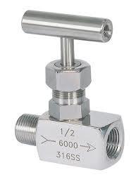
- Angle Needle Valve: These needle valves turn the output from the inlet by 90 degrees instead of in-line. The same operation concept applies, but the 90-degree angle can allow for better system integration. Figure 3 shows an example of an angle needle valve.
Needle valve selection:
When selecting a needle valve, four main characteristics and/or application requirements need to be taken into account: material, pressure, size, and temperature.
Material
The needle valve's housing material (Figure 2 callout E) is specified according to the application. The most common valve housing materials are brass and stainless steel due to their range of chemical resistance, however, there are also other materials available for special applications.
Needle Valve Applications:
Most constant pressure pump governors have needle valves to minimize the effects of fluctuations in pump discharge pressure. Needle valves are also used in some components of automatic combustion control systems where very precise flow regulation is necessary.
Needle Valve Body Designs
One type of body design for a needle valve is the bar stock body. Bar stock bodies are common, and, in globe types, a ball swiveling in the stem provides the necessary rotation for seating without damage.

Needle valves are frequently used as metering valves. Metering valves are used for extremely fine flow control. The thin disk or orifice allows for linear flow characteristics. Therefore, the number of handwheel turns can be directly correlated to the amount of flow. A typical metering valve has a stem with 40 threads per inch.
Needle valves generally use one of two styles of stem packing: an O-ring with TFE backing rings or a TFE packing cylinder. Needle valves are often equipped with replaceable seats for ease of maintenance.