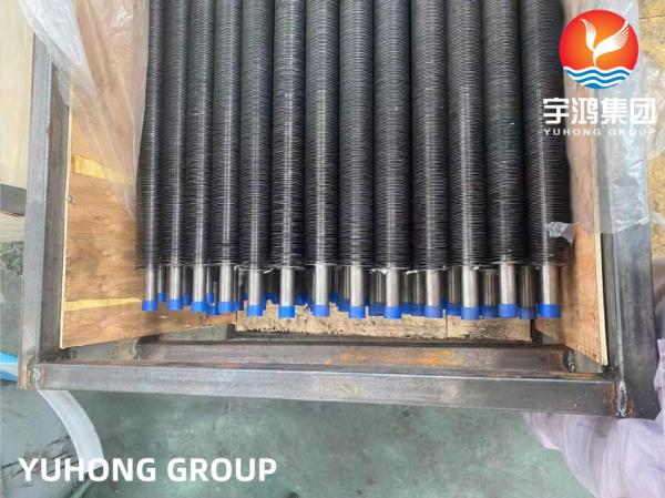
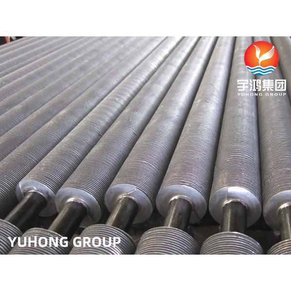
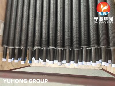
ASME SB163 N04400 G Type Embeded Fin Tube (Applied for Heat Exchanger)
There are various types of finned tubes that finned tube manufacturers produce. And the type required for a particular process depends on the process equipment unit.
G-Type finned tubes are known as embedded-fin tubes where g means grooved. They are formed by twisting a fin strip made of copper or aluminium into a machined groove and back-filling to secure the lock. Base tube material is filled. The G-type fin tube is strong as compared to other tubes. Hence, it is widely used where high-temperature heat transfer is required.
G-Type Finned Tube Features
In G-type finned tubes, the fins are prepared by embedding the metal strip into a groove. The latter is formed on a base tube. Placing the fin on it, back-filling is done – resulting in strong attachment of the fins to the base tubes. Hence, the name G-Fin Tubes has come up. The three processes mentioned above are carried out simultaneously. Maximum heat transfer is expected out of the g-fin tubes as the fins are strongly attached to the base tube.
The G-type finned tubes usually work at high temperature (with around 400 degree Celsius) applications. Made of copper, carbon, or aluminium, these fins have comparatively less resistance towards atmospheric corrosion. On the other hand, mechanical resistance is acceptable. Stainless steel and carbon steel fin materials are also used, but particular processing and tooling of the steel fin strips are necessary. Air coolers, radiators, etc use the g-fin tubes.
ube Chemical Composition
Grade | C | Mn | Si | S | Cu | Fe | Ni | Cr |
Monel 400 | 0.30 max | 2.00 max | 0.50 max | 0.24max | 28.0-34.0 | 2.50 max | 63.00 min | – |
Tube Mechanical Properties
Element | Density | Melting Point | Tensile Strength | Yield Strength (0.2%Offset) | Elongation |
Monel 400 | 8.8 g/cm3 | 1350 °C (2460 °F) | Psi – 80,000 , MPa – 550 | Psi – 35,000 , MPa – 240 | 40 % |
Tube Physical Properties
Properties | Metric | Imperial |
---|---|---|
Density | 8.8 gm/cm3 | 0.318 lb/in3 |
Tube Pressure Rating
Tube O.D. | Wall Thickness of Tube (inches) | |||||||
---|---|---|---|---|---|---|---|---|
.028 | .035 | .049 | .065 | .083 | .095 | .109 | .120 | |
Working Pressure (psig) | ||||||||
1/8 | 7900 | 10100 | ||||||
1/4 | 3700 | 4800 | 7000 | 9500 | ||||
5/16 | 3700 | 5400 | 7300 | |||||
3/8 | 3100 | 4400 | 6100 | |||||
1/2 | 2300 | 3200 | 4400 | |||||
3/4 | 2200 | 3000 | 4000 | 4600 | ||||
1 | 2200 | 2900 | 3400 | 3900 | 4300 |