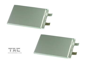
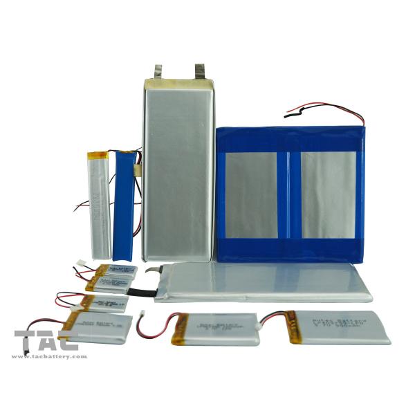
1.Battery specifications
No. | Items | Specifications | Remark
| |
1 | Capacity for assembled cell discharging by 0.2C
| ≥214.6Ah | Standard discharging method
| |
2 |
Battery Voltage
|
≥12.8
| Delivery voltage, Within 10 days from Factory
| |
3 |
Standard charge condition
| Charge with 0.2C constant current and 14.6Vconstant voltage, charge to 14.6V continue charging till current declineto ≤0.01C
| Charge voltage: 14.6V±0.02V Charge current:0.2C
| |
4 | Maximum charge current
|
|
10A | For continuous charging mod
|
5 | Maximum discharge current
|
| 10A | For continuous discharge mod
|
6 | Standard discharging method
|
0.2C constant current discharge to 8V, | 0.2C | |
7 | Internal Impedance
|
Assemblage Impedance
| Measure two sides of the drawing line after assembling.
| |
8 | Net | 23.5Kg | PACK |
2. Handling of Cells
2.1 Consideration of strength of film package
1) Soft Aluminum foil
Easily damaged by sharp edge parts such as pins and needles, Ni-tabs, so don’t strike by those sharp parts.
2) Sealed edge may be damaged by heat above 100°C, bend or fold sealed edge.
2.2 Prohibition short circuit
Never make short circuit cell. It generates very high current which causes heating of the cells and may cause electrolyte leakage, gassing
or explosion, that are very dangerous.
The LIP tabs may be easily short-circuited by putting them on conductive surface.
Such outer short circuit may lead to heat generation and damage of the cell.
An appropriate circuitry with PCM shall be employed to protect accidental short circuit of the battery pack.
2.3.Mechanical shock
LIP cells have less mechanical endurance than metal-can-cased LIB.
Falling, hitting, bending, etc. may cause degradation of LIP characteristics.
2.4 Handling of tabs
The battery tabs are not so stubborn especially for aluminum tab.
Don’t bend tab.
Do not bend tabs unnecessarily.
3. Notice for Designing Battery Pack
3.1 Pack toughness
Battery pack should have sufficient strength and the LIP cell inside should be protected from mechanical shocks.
3.2 Cell fixing
The LIP cell should be fixed to the battery pack by its large surface area. No cell movement in the battery pack should be allowed.
3.3 Inside design
No sharp edge components should be insides the pack containing the LIP cell.
3.4 Tab connection
Ultrasonic welding or spot welding is recommended for LIP tab connection method.
Battery pack should be designed that shear force are not applied to the LIP tabs.
If apply manual solder method to connect tab with PCM, below notice is very important to ensure battery performance:
1) The solder iron should be temperature controlled and ESD safe;
2) Soldering temperature should not exceed 350°C;
3) Soldering time should not be longer than 3s;