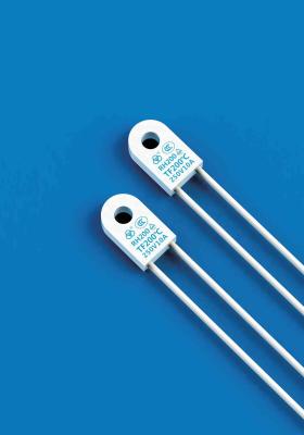
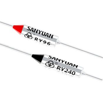
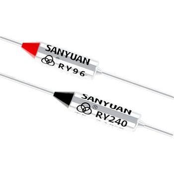
ZY14 SF Type 250V 10A 15A Coffee Pot Circuit Thermo Fuse Link UL VDE Certificated Little Thermal Cutout Switch
Product detail
To maximize product life, we suggest a 30℃ minimum differential between operating ambient temperature at the thermal cutoff location and your selected “Rated Functioning Temperature”.
Under no conditions should the thermal cutoff be exposed to a continuous normal ambient temperature in excess of 200℃.
Note: only proper testing of the above will help you in determining the selected thermal cutoff’s suitability within the application.
Temperature increasing according to UL standard: 1℃ / Min
TF (Rated Functioning Temperature)
The temperature of the thermal cutoff which causes it to change its state of conductivity with a detecion current up to 10 mA as the only load. Under the UL/IEC standards the tolerance is +0℃, -10℃.
TH (Holding Temperature)
The maximum temperature of the thermal cutoff at which it will not change its state of conductivity for 168 hours while conducting its rated voltage. It is called Th for short by UL and called Tc by IEC/VDE.
TM (Maximum Temperature Limit)
The tmperature of the thermal cutoff, up to which the mechanical and electrical properties of the thermal cutoff, having changed its state of conductivity, will not be impaired for 10 minutes.
Close Circuit
pellet:Made in Netherlands / United States
Star contact :Made in Japan 95% Silver
Epoxy: Made in Germany
Case&Lead Assembly:Made in Taiwan
Barrel Spring: Made in Taiwan
Trip Spring:Made in Taiwan
Bushing :Made in Korea
Open Circuit
Bottom Disc:Made in Japan
Top Disc:Made in Japan
Star Contact:Made in Japan 95% Silver
Bushing:Made in Korea
Contact Lead:Made in Taiwan
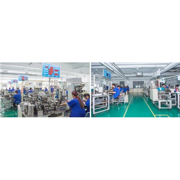
Production Capability, Precise Equipment
Fuse Installation Notes:
These notes are intended to be used to reduce the risk of malfunction of the thermal cutoff which may result from importer installation during forming of leads, splicing, welding and soldering
1. BENDING LEADS
The Fuse leads must be supported 1/8’’ from bend and case; And 1/8’’from bend and epoxy
2. MECHANICAL FORCES DURING APPLIANCE CONNECTION
a. When installing the Fuse, avoid unnecessary bending. twisting, pulling and pushing on the Fuse leads
b. Excessive clamping may cause denting or crushing of the Fuse body, which may cause failure
c. Note that the Fuse body is electrically live and must be insulated before applying a metal clamp over the Fuse body
3. SPLICES AND TERMIMATIONS
The connections must be electrically sound to prevent high resistance and secure enough to withstand the rated cutoff temperature.
4. SOLDERING LEADS
The fuse leads require heat sinking during soldering operations.
5. WELDING LEADS
To avoid welding internal parts, care should be taken that none of the welding current is conducted through the Fuse
6. EXAMINATION FOR DAMAGE
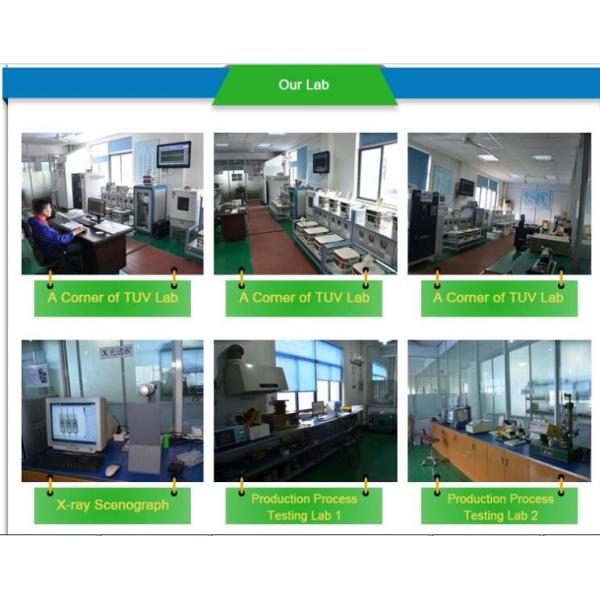
During prototype development .an examination for damage of the Fuse should be done after the device-to-appliance connections are made, X-raying before and after the assembly operation and close visual inspection with special attention made at the epoxy, should be performed
Thermal Cut-offs are a non-repairable item and that, in case of replacement, an equivalent thermal-link from the same manufacture and having the same catalog number should be used, mounted in exactly the same way.
always suggests and encourages customers to test samples of these devices to determine suitability within each appliance. Designers should be understand that overtemperture protection can be affected by installation and/or improper TCO location
. IMPORTANT NOTICE TO PURCHASER—Seller’s and Manufacture’s only obligation shall be to replace such quantity of the product proved to be defective, Neither seller nor manufacture shall be liable for any injury, loss or damage, direct or consequential, arising out of the use of or the inability to use the product