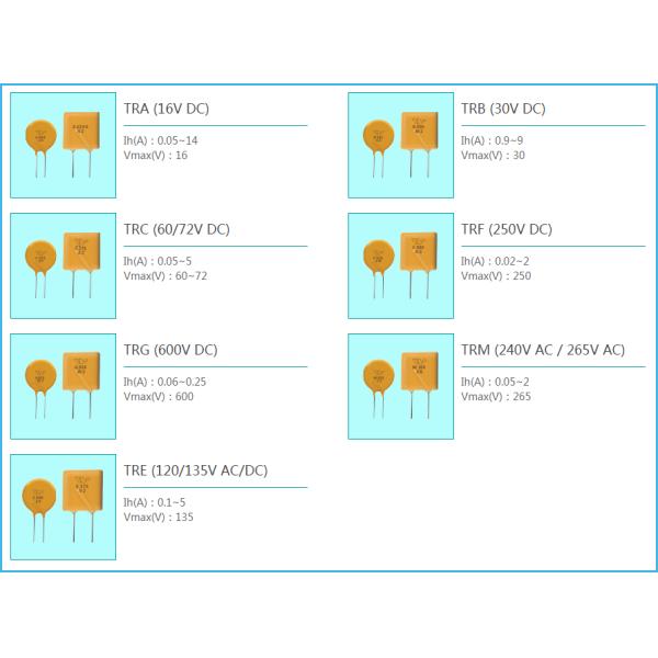
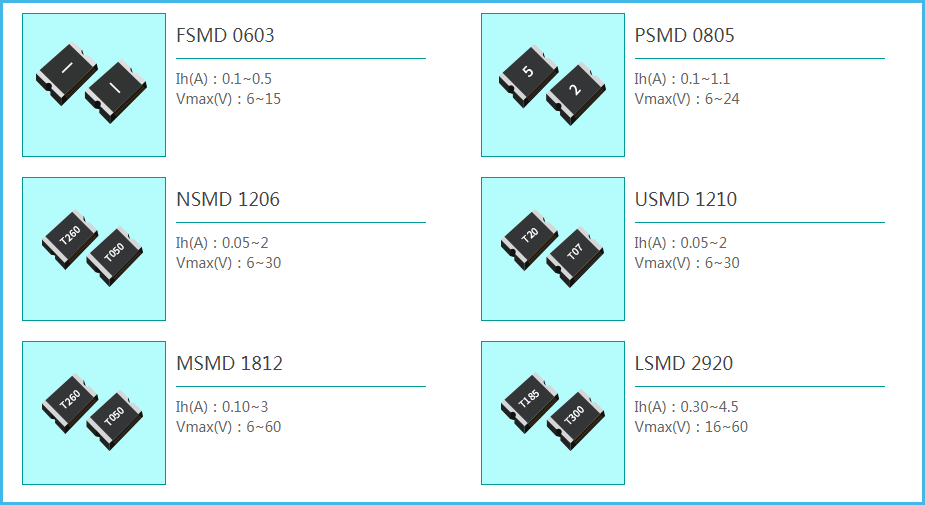
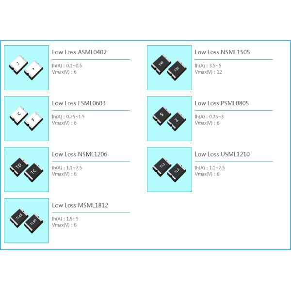
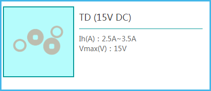
Dip Radial Leaded POLYMER PTC RESETTABLE FUSE TRF030 0.3A 250V For Lithium Battery
Features Of The PTC RESETTABLE FUSE
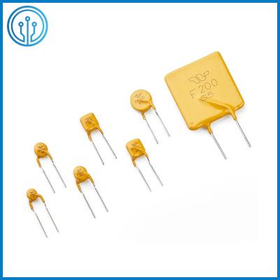
Radial lead type, multi-specification method
The encapsulation material is flame retardant and meets the requirements of UL94V0
Various packaging formats, bulk, tape and reel
Compliant with RoHS, Reach, HF, UL, C-UL, TUV
Application Of The PTC RESETTABLE FUSE
Telecommunications and Internet
UL 1950 and FCC Chapter 68 Specifications
ITU-T specification requirements
User terminal equipment
Analog/Analog Line Cards
T1/E1 equipment
ISDN equipment
ASDL equipment
HDSL equipment
Main Distribution Frame Security Unit
Wired Telephone/Central Office to Subscriber Cable
Massage chairs, kitchen appliances, small power motors
Computer motherboards, USB hubs, 485 ports and peripherals
Transformers, consumer electronics, security power supplies, satellite video receivers
Electrical Characteristics Of The PTC RESETTABLE FUSE
Part Number | IH (A) | IT (A) | Vmax OP Vdc | I max (A) | Vmax Interrupt Vrms | Ttrip (Max time to trip) | Pd typ (W) | R min (Ω) | R max (Ω) | R1max (Ω) | |
Current(A) | Time(S) | ||||||||||
TRF030 | 0.30 | 0.60 | 60 | 3.0 | 250 | 3.0 | 6.0 | 1.8 | 1.0 | 2.2 | 3.50 |
IH: Holding Current: maximum current at which the device will not trip in 25℃ still air.
IT: Tripping Current minimum current at which the device will trip in 25℃ still air.
Vmax: Maximum voltage device can withstand without damage at rated current.
I max: Maximum fault current device can withstand without damage at rated voltage.
T trip: Maximum time to trip(s) at assigned current.
Pd typ: Rated working power.
R min: Minimum resistance of device prior to trip at 25℃. R max: Maximum resistance of device prior to trip at 25℃.
R1 max: Maximum resistance of device is measured one hours post reflow at 25℃.
Series Specification Of The PTC RESETTABLE FUSE
P/N | IH(A) | IT(A) | Vmax(V) | I max(A) | T | T | Pd typ(W) | R min(Ω) | R max(Ω) |
(Max time to trip) | (Max time to trip) | ||||||||
(A) | (Sec) | ||||||||
TRF200 | 2 | 4 | 60 | 20 | 10 | 28 | 4.5 | 0.09 | 0.192 |
TRF150 | 1.5 | 3 | 60 | 15 | 7.5 | 25 | 3.5 | 0.12 | 0.28 |
TRF100 | 1 | 2 | 60 | 10 | 5 | 21 | 2.9 | 0.22 | 0.5 |
TRF080 | 0.8 | 1.6 | 60 | 8 | 4 | 18 | 3.6 | 0.32 | 0.8 |
TRF060 | 0.6 | 1.2 | 60 | 7 | 3 | 12 | 3.2 | 0.4 | 1.1 |
TRF050 | 0.5 | 1 | 60 | 6 | 3 | 10 | 3 | 0.56 | 1.4 |
TRF040 | 0.4 | 0.8 | 60 | 5.5 | 3 | 8 | 1.8 | 0.8 | 1.6 |
TRF030 | 0.3 | 0.6 | 60 | 3 | 3 | 6 | 1.8 | 1 | 2.2 |
TRF020 | 0.2 | 0.6 | 60 | 3 | 3 | 5 | 1.8 | 1.7 | 3.5 |
TRF018U | 0.18 | 0.54 | 60 | 3 | 3 | 1.5 | 1.8 | 1 | 2.2 |
TRF018 | 0.18 | 0.54 | 60 | 3 | 3 | 1.5 | 1.8 | 1 | 2.2 |
TRF014U | 0.145 | 0.29 | 60 | 3 | 1 | 2.5 | 1 | 3.5 | 6.5 |
TRF014 | 0.145 | 0.29 | 60 | 3 | 1 | 2.5 | 1 | 3 | 6 |
TRF012U | 0.12 | 0.24 | 60 | 3 | 1 | 1.5 | 1 | 6 | 10 |
TRF012 | 0.12 | 0.24 | 60 | 3 | 1 | 3 | 1 | 6 | 10 |
TRF011 | 0.11 | 0.22 | 60 | 3 | 1 | 1 | 1 | 6 | 12 |
TRF009 | 0.09 | 0.22 | 60 | 3 | 1 | 1 | 1 | 9.7 | 20.6 |
TRF008 | 0.08 | 0.16 | 60 | 3 | 0.35 | 4 | 1 | 14 | 22 |
TRF006 | 0.06 | 0.12 | 60 | 3 | 0.3 | 3 | 1 | 22 | 36 |
TRF004 | 0.04 | 0.08 | 60 | 3 | 0.2 | 3 | 1 | 24 | 65 |
TRF002 | 0.02 | 0.045 | 60 | 3 | 0.1 | 3 | 1 | 65 | 145 |
Package Information Of The PTC RESETTABLE FUSE
Packing quantity:1000pcs/bag
Tape and Reel : 1500 pcs/reel
Tape and Reel Specifications:Devices taped using EIA468–B/IEC286-2 standards.
Selection method Of The PTC RESETTABLE FUSE
In order to help you use the appropriate AMPFORT PPTC resettable fuse correctly, please choose according to the following methods.
1. List the average working current (I) value and working voltage (V) on the equipment line.
2. Select AMPFORT series resettable fuses according to I value, V value, product category and installation form.
3. If the internal ambient temperature of the device is greater than 20°C, the PTC phenomenon of the recoverable fuse will increase with the increase of temperature, and the supply of normal current will be maintained. The calculation is as follows: IH = working current (I) ÷ ambient temperature and Reduction rate of current value
4. Press the second step to select, the required IH should be greater than or equal to the IH value calculated in step 3.
If there is a requirement for the resistance value at room temperature and the action time of the overcurrent protection in the circuit, on the basis of selecting the corresponding series by the above method, select the corresponding element according to the resistance value at room temperature and the action time.