Surface Mount Ferrite Core Choke Multilayer Chip Inductor 0402 0603 0805 1206
Description Of The Multilayer Chip Inductor 0402 0603 0805 1206
Inductors are a form of passive component similar to a capacitor; they’re designed to deal with magnetism and control magnetic flux.
Inductors, also known as coils, chokes or reactors, are characterised by inductance, which is the ratio of the voltage to the rate of change of current. They’re frequently used in radio equipment to block AC and allow DC. An example of this passive component being used day-to-day is the ferrite bead on your laptop's power cable, which is designed for reducing electrical noise.
Inductors are usually a length of wire wound to create a coil around a core material with high insulator properties. However, inductors are more than just a coil of wire with an insulating material in the middle, in application, inductors are a key component to a circuit.
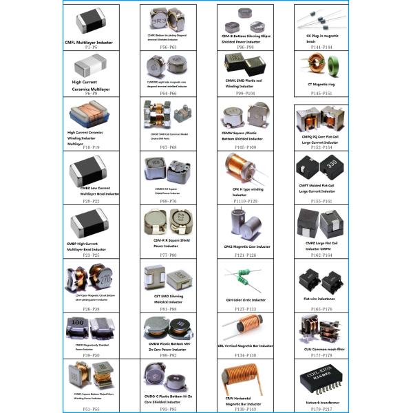
We sell several types of inductor:
* Wire-wound surface mount inductors – these are usually a wire coil wrapped around a magnetic component
* Leaded inductors - come in two main categories and are used in low and high voltage situations
* Multi-layer surface mount inductors - this is a style of coil which has several layers of wire wrapped around an inductor, with layers of insulation added to give a high inductance level.
We also carry inductor components for both EMI and RFI and a variety of wireless charging coils. Wireless charging coils are used for DC-DC currents and are used for inductive charging; any wireless charger runs using this inductive component.
Features Of The Multilayer Chip Inductor 0402 0603 0805 1206
Monolithic structure for high reliability,Excellect solderability and high heat resistance,No cross coupling due to magnetic shield,Low DCresistance and high current capability
* Monolithic Structure for high reliability.
* Small size inductor.
* No cross coupling due to magenetic shield.
* Perfact shape for mounting with no directionality.
* Excellent solderability and high heat resistance for reflow soldering or wave soldering.
* Operating temperature range: -55℃~125℃.
* Line-up with wide range of inductance values
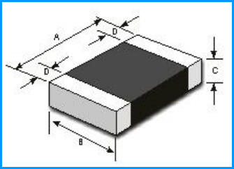
Size Of The Multilayer Chip Inductor 0402 0603 0805 1206 (mm)
PART NO. | A(mm) | B(mm) | C(mm) | D(mm) | MOQ |
CMFL0402 | 1.0±0.15 | 0.5±0.15 | 0.5±0.15 | 0.25±0.1 | 10000 Pcs/Reel |
CMFL0603 | 1.6±0.15 | 0.8±0.15 | 0.8±0.15 | 0.3±0.2 | 4000 Pcs/Reel |
CMFL0805 | 2.0±0.2 | 1.25±0.2 | 0.85±0.2 | 0.5±0.3 | 4000 Pcs/Reel |
1.25±0.2 | |||||
CMFL1206 | 3.2±0.2 | 1.6±0.2 | 0.85±0.2 | 0.5±0.3 | 4000 Pcs/Reel |
1.1±0.2 |
Specification Of The Multilayer Chip Inductor 0402 0603 0805 1206
CMFL0402 TYPE Chip Inductors
Part Number | Inductance | Min Quality Factor | L,Q Test Freq | Min.Self-resonan Frequency | Max.DC | Max.Rated Current | Thickness |
,L/Q | Resistance | ||||||
Units | UH | - | MHz | MHz | Ω | mA | mm(inch) |
Symbol | L0A | Q | Freq. | S.R.F | DCR | Ir | T |
CMFL0402-47NK | 0.047 | 10 | 50 | 220 | 0.45 | 25 | 0.5±0.15 |
CMFL0402-68NK | 0.068 | 10 | 50 | 210 | 0.45 | 25 | |
CMFL0402-82NK | 0.082 | 10 | 50 | 200 | 0.45 | 25 | |
CMFL0402-R10K | 0.1 | 10 | 50 | 200 | 0.8 | 25 | |
CMFL0402-R12K | 0.12 | 10 | 25 | 165 | 0.8 | 25 | |
CMFL0402-R15K | 0.15 | 10 | 25 | 140 | 0.9 | 25 | |
CMFL0402-R18K | 0.18 | 10 | 25 | 120 | 0.9 | 25 | |
CMFL0402-R22K | 0.22 | 10 | 25 | 110 | 1.2 | 25 | |
CMFL0402-R27K | 0.27 | 15 | 25 | 95 | 1.2 | 25 | |
CMFL0402-R33K | 0.33 | 15 | 25 | 85 | 1.25 | 18 | |
CMFL0402-R39K | 0.39 | 20 | 10 | 85 | 0.6 | 15 | |
CMFL0402-R47K | 0.47 | 20 | 10 | 80 | 0.7 | 15 | |
CMFL0402-R56K | 0.56 | 50 | 10 | 75 | 0.8 | 15 | |
CMFL0402-R68K | 0.68 | 20 | 10 | 70 | 0.9 | 15 | |
CMFL0402-R82K | 0.82 | 20 | 10 | 65 | 0.9 | 15 | |
CMFL0402-1R0K | 1 | 20 | 10 | 60 | 1 | 15 | |
CMFL0402-1R2K | 1.2 | 20 | 10 | 55 | 1.25 | 15 | |
CMFL0402-1R5K | 1.5 | 20 | 10 | 50 | 1.4 | 15 | |
CMFL0402-1R8K | 1.8 | 20 | 10 | 45 | 1.55 | 15 | |
CMFL0402-2R2K | 2.2 | 20 | 10 | 40 | 1.7 | 10 | |
CMFL0402-2R7K | 2.7 | 20 | 10 | 22 | 2 | 10 | |
CMFL0402-3R3K | 3.3 | 20 | 10 | 20 | 2.35 | 10 |
CMFL0603 TYPE Multilayer Chip Inductor
Part Number | Inductance | Min Quality | L,Q Test | Min.Self- | Max.DC | Max.Rated | Thickness |
resonant | |||||||
Factor | Freq,L/Q | Frequency | Resistance | Current | |||
Units | UH | - | MHz | MHz | Ω | mA | mm(inch) |
Symbol | L0A | Q | Freq. | S.R.F | DCR | Ir | T |
CMFL0603-R18K | 0.18 | 15 | 25 | 165 | 0.6 | 50 | 0.8±0.15 |
CMFL0603-R22K | 0.22 | 15 | 25 | 150 | 0.6 | 50 | |
CMFL0603-R27K | 0.27 | 15 | 25 | 136 | 0.8 | 50 | |
CMFL0603-R33K | 0.33 | 15 | 25 | 125 | 0.85 | 35 | |
CMFL0603-R39K | 0.39 | 15 | 25 | 110 | 1 | 35 | |
CMFL0603-R47K | 0.47 | 15 | 25 | 105 | 1.35 | 35 | |
CMFL0603-R56K | 0.56 | 15 | 25 | 95 | 1.55 | 35 | |
CMFL0603-R68K | 0.68 | 15 | 25 | 90 | 1.7 | 35 | |
CMFL0603-R82K | 0.82 | 15 | 25 | 85 | 2.1 | 25 | |
CMFL0603-1R0K | 1.0 | 35 | 10 | 90 | 0.7 | 25 | |
CMFL0603-1R2K | 1.2 | 35 | 10 | 85 | 0.8 | 25 | |
CMFL0603-1R5K | 1.5 | 35 | 10 | 80 | 0.95 | 25 | |
CMFL0603-1R8K | 1.8 | 35 | 10 | 75 | 1.15 | 25 | |
CMFL0603-2R2K | 2.2 | 35 | 10 | 70 | 1.25 | 15 | |
CMFL0603-2R7K | 2.7 | 35 | 10 | 45 | 1.35 | 15 | |
CMFL0603-3R3K | 3.3 | 35 | 10 | 40 | 1.55 | 15 | |
CMFL0603-3R9K | 3.9 | 35 | 10 | 35 | 1.7 | 15 | |
CMFL0603-4R7K | 4.7 | 35 | 10 | 33 | 2.1 | 15 | |
CMFL0603-5R6K | 5.6 | 35 | 4 | 22 | 1.55 | 5 | |
CMFL0603-6R8K | 6.8 | 35 | 4 | 20 | 1.7 | 5 | |
CMFL0603-8R2K | 8.2 | 35 | 4 | 18 | 2.1 | 5 | |
CMFL0603-100K | 10 | 30 | 2 | 17 | 1.85 | 3 | |
CMFL0603-120K | 12 | 30 | 2 | 15 | 2.1 | 3 | |
CMFL0603-150K | 15 | 20 | 1 | 14 | 1.7 | 1 | |
CMFL0603-180K | 18 | 20 | 1 | 13 | 1.85 | 1 | |
CMFL0603-220K | 22 | 20 | 1 | 11 | 2.1 | 1 | |
CMFL0603-270K | 27 | 20 | 1 | 10 | 2.75 | 1 | |
CMFL0603-330K | 33 | 20 | 1 | 9 | 2.95 | 1 |
CMFL0805 TYPE Multilayer Inductor
Part Number | Inductance | Min Quality | L,Q Test | Min.Self- | Max.DC | Max.Rated | Thickness |
Factor | Freq,L/Q | resonant | Resistance | Current | |||
Frequency | |||||||
Units | UH | - | MHz | MHz | Ω | mA | mm(inch) |
Symbol | L0A | Q | S.R.F | DCR | Ir | Ir | T |
CMFL0805-47NK | 0.047 | 15 | 50 | 320 | 0.2 | 300 | 0.85±0.2 |
CMFL0805-68NK | 0.068 | 15 | 50 | 280 | 0.2 | 300 | |
CMFL0805-82NK | 0.082 | 15 | 50 | 255 | 0.2 | 300 | |
CMFL0805-R10K | 0.1 | 20 | 25 | 235 | 0.3 | 250 | |
CMFL0805-R12K | 0.12 | 20 | 25 | 220 | 0.3 | 250 | |
CMFL0805-R15K | 0.15 | 20 | 25 | 200 | 0.4 | 250 | |
CMFL0805-R18K | 0.18 | 20 | 25 | 185 | 0.4 | 250 | |
CMFL0805-R22K | 0.22 | 20 | 25 | 170 | 0.5 | 250 | |
CMFL0805-R27K | 0.27 | 20 | 25 | 150 | 0.5 | 250 | |
CMFL0805-R33K | 0.33 | 20 | 25 | 145 | 0.55 | 250 | |
CMFL0805-R39K | 0.39 | 25 | 25 | 135 | 0.65 | 250 | |
CMFL0805-R47K | 0.47 | 25 | 25 | 125 | 0.65 | 250 | |
CMFL0805-R56K | 0.56 | 25 | 25 | 115 | 0.75 | 150 | |
CMFL0805-R68K | 0.68 | 25 | 25 | 105 | 0.8 | 150 | |
CMFL0805-R82K | 0.82 | 25 | 25 | 100 | 1 | 150 | |
CMFL0805-1R0K | 1.0 | 45 | 10 | 95 | 0.4 | 50 | |
CMFL0805-1R2K | 1.2 | 45 | 10 | 85 | 0.5 | 50 | |
CMFL0805-1R5K | 1.5 | 45 | 10 | 80 | 0.5 | 50 | |
CMFL0805-1R8K | 1.8 | 45 | 10 | 75 | 0.6 | 50 | |
CMFL0805-2R2K | 2.2 | 45 | 10 | 70 | 0.65 | 30 | |
CMFL0805-2R7K | 2.7 | 45 | 10 | 45 | 0.75 | 30 | |
CMFL0805-3R3K | 3.3 | 45 | 10 | 41 | 0.8 | 30 | |
CMFL0805-3R9K | 3.9 | 45 | 10 | 38 | 0.9 | 30 | |
CMFL0805-4R7K | 4.7 | 45 | 10 | 35 | 1 | 30 | |
CMFL0805-5R6K | 5.6 | 50 | 4 | 32 | 0.9 | 15 | |
CMFL0805-6R8K | 6.8 | 50 | 4 | 29 | 1 | 15 | |
CMFL0805-8R2K | 8.2 | 50 | 4 | 26 | 1.1 | 1 |
CMFL1206 TYPE
Part Number | Inductance | Min Quality | L,Q Test | Min.Self- | Max.DC | Max.Rated | Thickness |
Factor | Freq,L/Q | resonant | Resistance | ||||
Frequency | Current | ||||||
Units | UH | - | MHz | MHz | Ω | mA | mm(inch) |
Symbol | L0A | Q | Freq. | S.R.F | DCR | Ir | T |
CMFL1206-47NK | 0.047 | 20 | 50 | 320 | 0.15 | 300 | 0.85±0.2 |
CMFL1206-68NK | 0.068 | 20 | 50 | 280 | 0.25 | 300 | |
CMFL1206-R10K | 0.1 | 20 | 25 | 235 | 0.25 | 250 | |
CMFL1206-R12K | 0.12 | 20 | 25 | 220 | 0.3 | 250 | |
CMFL1206-R15K | 0.15 | 20 | 25 | 200 | 0.3 | 250 | |
CMFL1206-R18K | 0.18 | 20 | 25 | 185 | 0.4 | 250 | |
CMFL1206-R22K | 0.22 | 20 | 25 | 170 | 0.4 | 250 | |
CMFL1206-R27K | 0.27 | 20 | 25 | 150 | 0.5 | 250 | |
CMFL1206-R33K | 0.33 | 25 | 25 | 145 | 0.6 | 250 | |
CMFL1206-39K | 0.39 | 25 | 25 | 135 | 0.5 | 200 | |
CMFL1206-R47K | 0.47 | 25 | 25 | 125 | 0.6 | 200 | |
CMFL1206-R56K | 0.56 | 25 | 25 | 115 | 0.7 | 150 | |
CMFL1206-R68K | 0.68 | 25 | 25 | 105 | 0.8 | 150 | |
CMFL1206-R82K | 0.82 | 25 | 25 | 100 | 0.9 | 150 | |
CMFL1206-1R0K | 1.0 | 45 | 10 | 65 | 0.4 | 100 | |
CMFL1206-1R2K | 1.2 | 45 | 10 | 60 | 0.5 | 100 | |
CMFL1206-1R5K | 1.5 | 45 | 10 | 55 | 0.5 | 50 | |
CMFL1206-1R8K | 1.8 | 45 | 10 | 50 | 0.5 | 50 | |
CMFL1206-2R2K | 2.2 | 45 | 10 | 45 | 0.6 | 50 | |
CMFL1206-2R7K | 2.7 | 45 | 10 | 41 | 0.6 | 50 | |
CMFL1206-3R3K | 3.3 | 45 | 10 | 38 | 0.7 | 50 | |
CMFL1206-3R9K | 3.9 | 45 | 10 | 35 | 0.8 | 50 | |
CMFL1206-4R7K | 4.7 | 45 | 10 | 32 | 0.9 | 50 | |
CMFL1206-5R6K | 5.6 | 50 | 4 | 29 | 0.7 | 25 | |
CMFL1206-6R8K | 6.8 | 50 | 4 | 26 | 0.8 | 25 | |
CMFL1206-8R2K | 8.2 | 50 | 4 | 24 | 0.8 | 25 | |
CMFL1206-100K | 10 | 50 | 2 | 22 | 1 | 25 | |
CMFL1206-120K | 12 | 50 | 2 | 19 | 1.05 | 15 | |
CMFL1206-150K | 15 | 35 | 1 | 18 | 0.7 | 5 | |
CMFL1206-180K | 18 | 35 | 1 | 16 | 0.7 | 5 | |
CMFL1206-220K | 22 | 35 | 1 | 15 | 0.8 | 5 | |
CMFL1206-270K | 27 | 35 | 1 | 14 | 0.9 | 5 | |
CMFL1206-330K | 33 | 35 | 0.4 | 13 | 1.05 | 5 | 1.1±0.2 |
CMFL1206-470K | 47 | 40 | 2 | 10 | 3 | 5 | |
CMFL1206-680K | 68 | 40 | 1 | 9 | 3.4 | 4 | |
CMFL1206-101K | 100 | 40 | 1 | 8 | 3.8 | 4 |
Applications Of The Multilayer Chip Inductor 0402 0603 0805 1206
■ Used for choke of power lines, such as DVC/DSC/MD and other modules
■ Widely used in communications,video and audio and equipment, Computer,Remote contol,ETC.
■ Matching circuits of RF units choke circuits
■ Mobile phones
■ Cellular phones
■ CTV, VCR, HIC, FDD
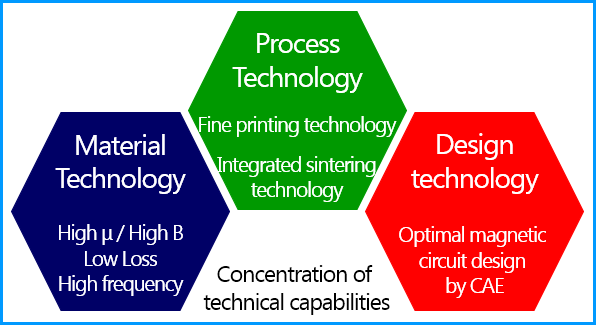
The Advantage of Multilayer Technology
• Feasible to produce small and slim type components
• Suitable for mass production
• Ensure supplying stability and short delivery period.
• Full automatic process to ensure high reliability and quality.
QUALITY CONTROL ON TESTING Of The Multilayer Chip Inductor 0402 0603 0805 1206
Full-Automatic Testing
All passive electronic components are inspected by the auto-separation machine in order to identify defective products.
DCR Testing
Each finished product will go through a DCR testing by the ohmmeter to improve long term reliability in the electronic systems.
Impedance Testing
In this examination, the impedance analyzing instrument will be used to confirm the impedance value meet the standard for the long-lasting usage.
Frequency Testing
Frequency testing to ensure every part meets industry standards by the impedance analyzer and exceeds customer expectations.
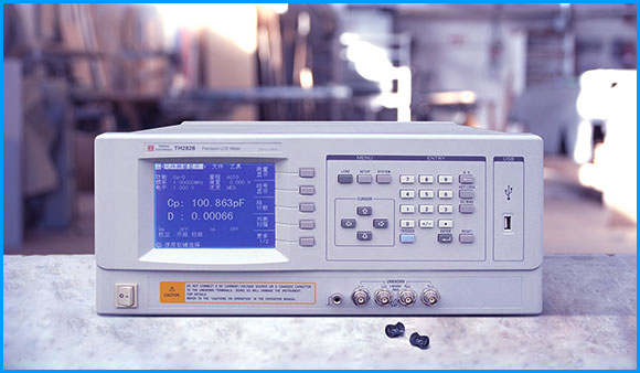
Q Factor Value Testing
This test serves to demonstrate that each passive electronic component reaches a good impact on the performance by LCR meter.