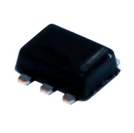
PART NUMBER | PACKAGE | BODY SIZE (NOM) | ||||||||||
TMP112x | SOT563 (6) | 1.60 mm × 1.20 mm |
1 Features
1• TMP112A Accuracy Without Calibration :
– 0.5°C (Maximum) From 0°C to +65°C (3.3 V)
– 1.0°C (Maximum) From –40°C to +125°C
• TMP112B Accuracy Without Calibration :
– 0.5°C (Maximum) From 0°C to +65°C (1.8 V)
– 1.0°C (Maximum) From –40°C to +125°C
• TMP112N Accuracy Without Calibration:
– 1.0°C (Maximum) From –40°C to +125°C
• SOT563 Package (1.6 mm × 1.6 mm)
• Low Quiescent Current:
– 10-μA Active (Maximum), 1-μA Shutdown
(Maximum)
• Supply Range: 1.4 V to 3.6 V
• Resolution: 12 Bits
• Digital Output: SMBus™, Two-Wire, and I
2C
Interface Compatibility
• NIST Traceable
2 Applications
• Portable and Battery-Powered Applications
• Power-Supply Temperature Monitoring
• Computer Peripheral Thermal Protection
• Notebook Computers
• Battery Management
• Office Machines
• Thermostat Controls
• Electromechanical Device Temperatures
• General Temperature Measurements:
– Industrial Controls
– Test Equipment
– Medical Instrumentation
3 Description
The TMP112 family of devices are digital temperature
sensors designed for high-accuracy, low-power,
NTC/PTC thermistor replacements where high
accuracy is required. The TMP112A and TMP112B
offers 0.5°C accuracy and are optimized to provide
the best PSR performance for 3.3V and 1.8V
operation respectively, while TMP112N offers 1°C
accuracy. These temperature sensors are highly
linear and do not require complex calculations or
lookup tables to derive the temperature. The on-chip
12-bit ADC offers resolutions down to 0.0625°C.
The 1.6-mm × 1.6-mm SOT563 package is 68%
smaller footprint than an SOT23 package. The
TMP112 family features SMBus, two-wire and I
2C
interface compatibility, and allows up to four devices
on one bus. The device also features an SMBus alert
function. The device is specified to operate over
supply voltages from 1.4 to 3.6 V with the maximum
quiescent current of 10 µA over the full operating
range.
The TMP112 family is designed for extended
temperature measurement in communication,
computer, consumer, environmental, industrial, and
instrumentation applications. The device is specified
for operation over a temperature range of –40°C to
+125°C.
The TMP112 family production units are 100% tested
against sensors that are NIST-traceable and are
verified with equipment that are NIST-traceable
through ISO/IEC 17025 accredited calibrations.
Specifications
6.1 Absolute Maximum Ratings
over operating free-air temperature range (unless otherwise noted)(1)
MIN MAX | UNIT | ||||||||||||||||||||||||||
Supply voltage | V+ | 4 | V | ||||||||||||||||||||||||
Voltage at SCL, ADD0, and SDA | –0.5 4 | V | |||||||||||||||||||||||||
Voltage at ALERT | –0.5 ((V+) + 0.3) and ≤ 4 | V | |||||||||||||||||||||||||
Operating temperature | –55 150 | °C | |||||||||||||||||||||||||
Junction temperature, TJ | 150 | °C | |||||||||||||||||||||||||
Storage temperature, Tstg | –60 150 | °C |
(1) Stresses beyond those listed under Absolute Maximum Ratings may cause permanent damage to the device. These are stress ratings only, which do not imply functional operation of the device at these or any other conditions beyond those indicated under Recommended Operating Conditions. Exposure to absolute-maximum-rated conditions for extended periods may affect device reliability.
Pin Functions | ||||||||||||||||||||||||||||
PIN | I/O | DESCRIPTION | ||||||||||||||||||||||||||
NO. | NAME | |||||||||||||||||||||||||||
1 | SCL | I | Serial clock. Open-drain output; requires a pullup resistor. | |||||||||||||||||||||||||
2 | GND | — | Ground | |||||||||||||||||||||||||
3 | ALERT | O | Overtemperature alert. Open-drain output; requires a pullup resistor. | |||||||||||||||||||||||||
4 | ADD0 | I | Address Select. Connect to V+, GND, SDA or SCL | |||||||||||||||||||||||||
Pin Functions (continued) | ||||||||||||||||||||||||||||
PIN | I/O | DESCRIPTION | ||||||||||||||||||||||||||
NO. | NAME | |||||||||||||||||||||||||||
5 | V+ | I | Supply voltage, 1.4 V to 3.6 V | |||||||||||||||||||||||||
6 | SDA | I/O | Serial data. Open-drain output; requires a pullup resistor. |
6.3 Recommended Operating Conditions
over operating free-air temperature range (unless otherwise noted)
MIN | NOM | MAX | UNIT | |||||||||||||||||||||||||
V+ | Supply voltage | 1.4 | 3.3 | 3.6 | V | |||||||||||||||||||||||
TA | Operating free-air | temperature | –40 | 125 | °C | |||||||||||||||||||||||
6.4 Thermal Information | ||||||||||||||||||||||||||||
THERMAL METRIC(1) | TMP112 | UNIT | ||||||||||||||||||||||||||
DRL (SOT563) | ||||||||||||||||||||||||||||
6 PINS | ||||||||||||||||||||||||||||
RθJA | Junction-to-ambient thermal resistance | 210.3 | °C/W | |||||||||||||||||||||||||
RθJC(top) | Junction-to-case (top) thermal resistance | 105.0 | °C/W | |||||||||||||||||||||||||
RθJB | Junction-to-board thermal resistance | 87.5 | °C/W | |||||||||||||||||||||||||
ψJT | Junction-to-top characterization parameter | 6.1 | °C/W | |||||||||||||||||||||||||
ψJB | Junction-to-board characterization parameter | 87.0 | °C/W | |||||||||||||||||||||||||
RθJC(bot) | Junction-to-case (bottom) thermal resistance | N/A | °C/W |