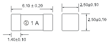
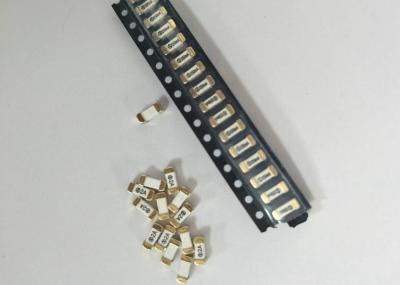
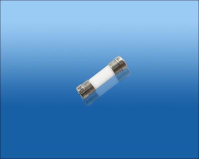
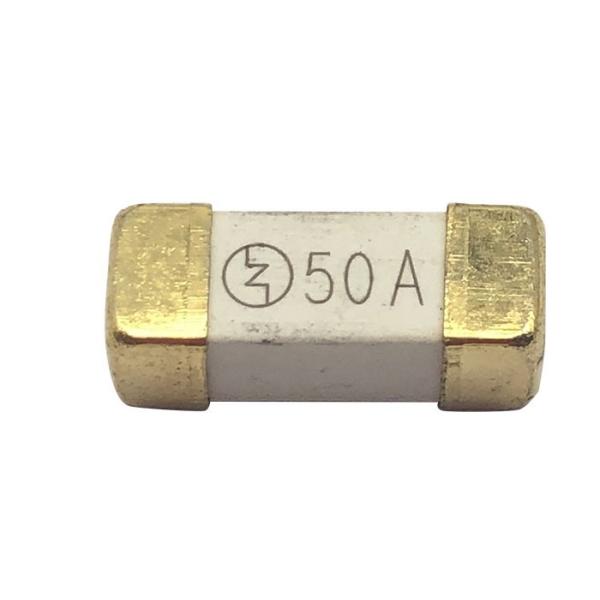
High Inrush Surface Mount Package Ceramic Fast Acting Micro Fuse 2A 300V 6.1x2.5 mm SSF1200
Automated Equipment Production Line
90% of the automated production equipment is crafted in-house, which greatly enhances production efficiency and the quality of our products
Certification
Agency | Ampere Range | Agency File Number |
UL | 50mA ~ 7A | E340427(JDYX2) |
CUL | 50mA ~ 7A | E340427(JDYX8) |
Specification
Catalog | Ampere | Voltage | Breaking | Nominal Cold | I2TMelting |
No. | Rating | Rating | Capacity | Resistance(Ohms) | Integral(A2.S) |
SSF0250 | 250mA | 300VAC | 50A@300VAC 50A@250VAC 200A@125VAC | 0.86 | 0.145 |
SSF0300 | 300mA | 0.62 | 0.162 | ||
SSF0315 | 315mA | 0.55 | 0.189 | ||
SSF0375 | 375mA | 0.47 | 0.2 | ||
SSF0400 | 400mA | 0.38 | 0.238 | ||
SSF0500 | 500mA | 0.32 | 0.275 | ||
SSF0600 | 600mA | 0.285 | 0.47 | ||
SSF0630 | 630mA | 0.256 | 0.566 | ||
SSF0700 | 700mA | 0.208 | 0.805 | ||
SSF0750 | 750mA | 0.175 | 1.24 | ||
SSF0800 | 800mA | 0.155 | 1.88 | ||
SSF1100 | 1A | 0.148 | 3.5 | ||
SSF1125 | 1.25A | 0.102 | 4.76 | ||
SSF1150 | 1.5A | 0.085 | 6.305 | ||
SSF1200 | 2A | 0.044 | 8.95 | ||
SSF1250 | 2.5A | 0.043 | 16.025 | ||
SSF1300 | 3A | 0.033 | 21.56 | ||
SSF1315 | 3.15A | 0.029 | 22.75 | ||
SSF1350 | 3.5A | 0.027 | 27.05 | ||
SSF1400 | 4A | 0.025 | 31.808 | ||
SSF1500 | 5A | 0.019 | 40.25 | ||
SSF1600 | 6A | 0.018 | 67.245 | ||
SSF1630 | 6.3A | 0.017 | 73.55 | ||
SSF1700 | 7A | 0.015 | 76.28 |
Melting Time
% of Ampere Rating(In) | Blowing Time |
100% * In | 4 hours Min |
200% * In | 120 sec Max |
Safety Decaying Factors
Test results may differ between laboratory testing and actual circuit application, due to contacting resistance from different types of fuse clip/holder used and circuit layouts. Please refer to safety decaying factor calculation guide listed below, to ensure proper fuse functioning within 25±5°C.
♦ UL standard fuse: current rating (In)= the maximum steady current of circuit / 0.75
♦ IEC standard fuse:current rating (In)= the maximum steady current of circuit / 0.90
♦ JIS standard fuse: current rating (In)= the maximum steady current of circuit / 0.85
List of Inspection Items
Salt spray test
Digital microscope test
Isolation test
Thermal shock
Soldering heat resistance test
Temperature raising test
Environmental test
Plated-thickness major material analysis
Steps For Fuse Selection
1)Fuse Physical Size ► 2) Safety Agency Approvals ► 3)Voltage Rating ► 4)Current Rating ► 5)Pulse ► 6)Selection for Fuse Specific Specification ► 7)Tested in the Actual Circuit
What's the difference between the slow blow and fast acting fuse in terms of performance and application?
A slow blow fuse is different from a fast acting fuse in its capability to withstand transient pulse currents, i.e., it can withstand the surge current upon power-on/off, thus ensuring the equipment works normally. Therefore, slow blow fuses are often called time-delay fuses. Technically, a slow blow fuse features a higher I2t value, and it requires more energy to blow, so it is more capable of withstanding pulses compared with a fast acting fuse of same rated current.
When an overcurrent occurs in a circuit, the breaking time of a slow blow fuse takes longer than that of a fast acting fuse because of the larger I2t. Is it less protected this way as some people are worried? The answer is no. Once the circuit fails, the overcurrent will last and corresponding energy released will go beyond the I2t of the fuse until it blows out. The timing difference of slow blowing and fast acting is not significant to their protection. Slow blowing will affect the protection performance only when sensitive components existing in the protected circuit need to be protected.
Due to the previous difference, slow blow and fast acting fuses are applied to different circuits. Fast acting fuses must be used in purely resistive circuits (no or fewer surges) or the circuits where IC and other sensitive components need to be protected, while slow blow fuses are preferably used in capacitive or sensitive circuits where surges occur upon power-on/off and power input/output. Apart from circuits for IC protection, most applications with fast acting fuses can be replaced with slow blow ones to enhance anti-surge capability. Contrarily, replacement of applications with slow blow fuses to fast acting ones may cause the fuse to break as soon as the equipment is switched on and fails to work.
Furthermore, economic consideration is also an indirect factor for selection because a slow blow fuse is much expensive than a fast acting one.