UL1434 CQC TUV Certificated MF12 MF11 Temperature Compensation NTC Thermistor For Measuring Equipments
PDF Specification Download Link : MF11 Temperature Compensation NTC Thermistor.pdf
General
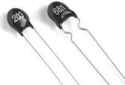
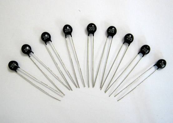
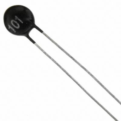
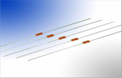
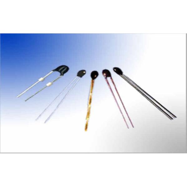
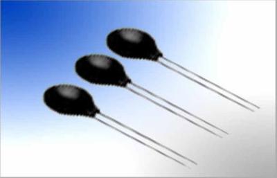
Temperature Compensation NTC Thermistor. The MF11 series of NTC Thermistors is designed for temperature measurement and the temperature compensation of measurement instruments and electronic circuits.
Characteristics
Application
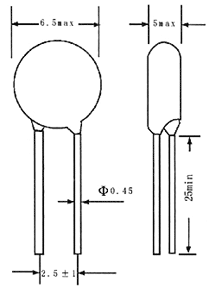
Dimension (Unit:mm)
Specification
Part No | B Value (25/50ƒC) | Rated zero-power resistance at 25ƒC | ||
Rated Value (K) | Allowable Tolerance (%) | Resistance range (Ω) | Allowable Tolerance (%) | |
MF11 | 2600 4400 4500 4600 4750 | +/-10 | 5-7 80000-144000 145000-199000 200000-299000 300000-500000 | +/- 5 +/-15 |
Remark: We can produce thermistors according to your special requirements.
Power-Consumption Curve
Mechanical Requirements
Item | Requirements | Test Method |
1.Solder-ability | The terminals shall be uniformly tinned, and its area≥95% | Dipping theNTC terminals to a depth of 15mm in a soldering bath of 245±5℃ and to the place of 6mm far from NTC body for 3±0.5s (See IEC68-2-20 /GB2423.28 Ta ) |
2.Resistance To Soldering Heat | No visible mechanical damage. ΔR/RN ≤20% (ΔR =∣RN-RN'∣) | Dipping the NTC terminals to a depth of 15mm in a soldering bath of 260±5℃ and to the place for 6mm below from NTC body for 3±0.5s.After recovering4-5h under 25±2℃. The rated zero power resistance value RN' shall be measured. (See IEC68-2-20 /GB2423.28 Tb) |
3.Strength of lead terminal | No break out ΔR/RN ≤20% (ΔR =∣RN-RN'∣) | Fasten the body and apply a force gradually to each lead until 10N and then keep for 10sec, Hold body and apply a force to each lead until 90°slowly at 5N in the direction of lead axis and then keep for 10sec, and do this in the opposite direction repeat for other terminal. After recovering 4~5h under 25±2℃, the rated zero power resistance value RN' shall be measured. (See IEC68-2-21/GB2423.29 Ua / Ub) |
Reliability Test
Item | Requirements | Test Method |
1.Temp. Cycling Testing | No visible mechanical damage. ΔRN / RN ≤20% (ΔR =∣RN-RN'∣) | Ta:-40±3℃/ 30min→25±2℃/ 5min→ Tb:160±3℃/ 30min→25±2℃/ 5min Cycles: 5times After recovering 4~5 h under 25±2℃, the rated zero power resistance value RN' shall be measured. |
2.Electrical Cycling Testing | Ambient temp. Range:25℃±2℃. Cycles: 2,000times On / Off: 5 s / 55 s Test Current: 7A After recovering 4~5h under 25±2℃, the rated zero power resistance value RN' shall be measured. | |
3.LoadLife ( Endurance ) Testing | Ambient temp. Range:25℃±2℃; 7A/ 1,000±24h After recovering 4~5 h under 25±2℃, the rated zero power resistance value RN' shall be measured. | |
4. Humidity Testing | No visible mechanical damage. ΔRN / RN ≤20% (ΔR =∣RN-RN'∣) | Ambient temp. range : 40℃±2℃ R.H.:93±3% , Energized time:1000±24 h After recovering 4~5 h under 25±2℃, the rated zero power resistance value RN' shall be measured. |