Specification:
Specification Performance | HS520A |
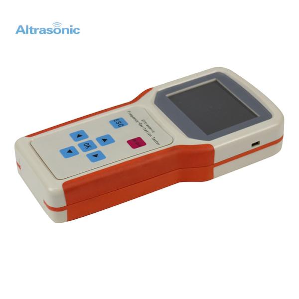
Product feature | Portable, 8inch screen, Full touch screen |
Dimension | L24cm,W19cm,H10cm |
Frequency range | 1KHz~hz |
Measurement Index | All the parameters, the graph |
Measurement Accuracy | < 0.5% |
Measurement Speed | 5s/one pass(600scan point) Adjustable |
Frequency Accuracy | ±10ppm |
Phase Resolution | 0.15 degree |
Environment Temperature | 10~40degree centigrade |
Impedance Range | 1Ω~1MΩ |
Frequency Step | 0.1Hz~any |
Power Supply | AC100V~AC250V,50~60Hz, 30W |
Application | Ultrasonic device |
Description:
Ultrasonic Analyzer HS520A is jointly developed by the Automation department of China Tsinghua University and the Chinese Academy of Sciences. It was widely used in the detection of piezoelectric ultrasonic devices and equipment of integrated solutions.
HS520A, Comparing with HS70A-P(computer)and HS70A-D(on board display version),it is a new generation of ultrasonic components analyzer which based on the combination of the advantages of the previous devices.
Characteristics are as following:
2. Relies on the new powerful ARM processor data processing capacity, HS520A measurement accuracy is much higher than HS70A-D(with display version), can achieve HS70A-P(computer version) level.
4. Connecting the computer to operate as HS70V-P. The software is fully compatible, the user are no longer familiar with software operation.
6. HS520A operation is no longer based on Windows system, with long-term reliable operation capacity in the production line.
Measuring graphics and data
1. Graphical introduction
The system displays “admittance circle graph” + “logarithm graph”
Admittance circle graph: the trajectory of the admittance as a function of frequency in the polar coordinate system.
Logarithm graph: the red line is the logarithm curve of the impedance amplitude and the blue line is the impedance phase curve.
You can click“LgZ/GB-F”to display the admittance curve, the red line is the admittance real part, and the blue line is the admittance imaginary part.
2. Parameters description:
Fs:resonant frequency
F1and F2:Half power point
Gmax:Maximum conductance
R1:Dynamic impedance
Fp:Antiresonant frequency
Qm:Mechanical quality factor
CT:Capacitance
L1:Dynamic inductance
C1:Dynamic capacitance
C0:Static capacitance
Keff:Effective electromechanical coupling coefficient
Kp:Plane electromechanical coupling coefficient
Pm:The phase value of the resonant frequency point
Zm:Minimum impedance value
Fm:Minimum impedance frequency
Application:
Piezoelectric ceramics, transducers, ultrasonic cleaning machines, ultrasonic plastic welding machine, underwater acoustic, magnetostrictive materials, ultrasonic grinder, ultrasonic atomization , reversing radar, ultrasonic ranging, phacoemulsification , ultrasonic motors, and all other devices used in piezoelectric and ultrasound.
Large Frequency Range 1-hz Newest Accurate Measuring Device Horn Analyzer For Sonotrode Frequency Testing
Workshop:
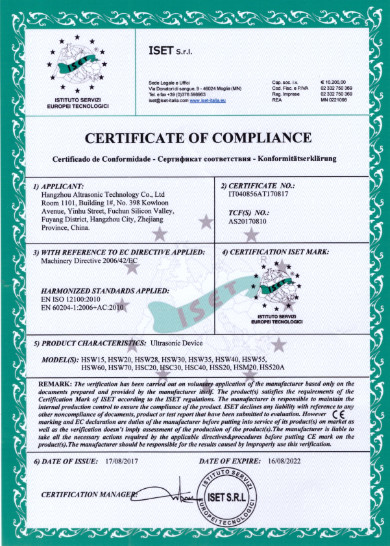
CE Certification:
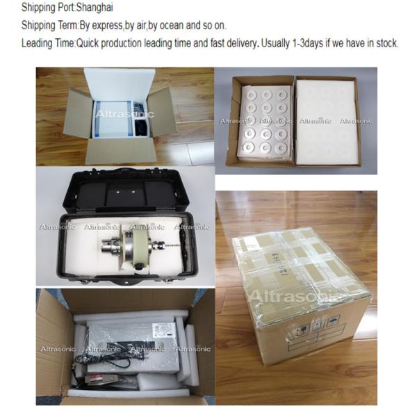
Packing&Shipping:
Payment: