150W DC 24V Brushless Motor Automatic Boom Barrier With Wireless Remote Control
1. Selection of spring
The spring is stretchable one and
the specification is as follows:
Diameter 4.0MM green color
Diameter 4.5MM red color
Diameter 5.5MM blue color
Diameter 6.8MM yellow color
Diameter 7.0MM white color
1 The running speed can be adjusted from 2.5s to 8s |
2 Arm can be quickly interchanged. |
3 Open the barrier gate by motor wheel when power off ,automatically reset after power on |
4 Curved crank arm three- link movement structure, the operation is stable |
5 Wireless remote control control open/close |
6 Auto reverse function(force adjustable) |
7 Infrared photocells connector is available |
8 Loop detector connector is available. |
9 Well-integrated with car parking system equipment,with wire control(must be switch signal) |
10 Connector for traffic light(AC220V,power less than 40W) |
1 Working temperature(motor): -30℃~+70℃ |
2 Rated voltage:DC24V |
3 Running speed:2.5s-8s |
4 Rated current:9.5A |
5 Rated power:150W |
6 No-load speed:1850rpm |
7 Rated speed:1400rpm |
8 Rated torque:59.6N.m |
9 Relative humidity:≥85% |
10 Remote control distance:≤100M(in the open place) |
5.Electrical installation, wiring diagram
1. The internal wiring of this machine has been completed when it leaves the factory, please do not change it, just connect the 220V power supply and the protective ground wire to work.
2. Traffic light interface: 2A24V voltage traffic light use.
3. Infrared anti-smashing interface: external infrared anti-radiation device, and the switch signal of the anti-radiation output can be connected.
4. Ground sense interface: support external ground sense. When using an external ground sensor, you only need to connect the switch signal output by the ground sensor.
5. Parking system interface wire control interface: connect the switch signal from the system to this interface to control the barrier.
6. Starting limit and landing limit signal output: output COM/NO/NC switch signal to the system to inform the current state of the barrier.
7. RS485 or CAN communication interface: PC software can be used to manage more than 15 barriers.
6.Function setting parameter table
Menu code | Parameter Scale | Parameter name | Default | Unit | Remark | |||
H00-00 | 25-95 | Open speed adjustment | 40 | Corresponding PWM duty cycle 25%-95%, step size is 1 | ||||
H00-01 | 25-95 | Close speed adjustment | 40 | Corresponding PWM duty cycle 25%-95%, step size is 1 | ||||
H00-02 | 5-40 | Open in place decelerate angle | 35 | The larger the angle value, the less likely it is to shake the arm when it is in place. | ||||
H00-03 | 5-40 | Close in place decelerate angle | 35 | The larger the angle value, the less likely it is to shake the arm when it is in place. | ||||
H00-04 | 1-20 | Open accelerate adjustment | 1 | ms | The smaller the number, the faster the speed | |||
H00-05 | 1-20 | Close accelerate adjustment | 8 | ms | The smaller the number, the faster the speed | |||
H00-06 | 1-30 | Open in place angle | 1 | degree | step size is 1, when big than 11, will automatically check one side | |||
H00-07 | 1-30 | Close in place angle | 1 | degree | step size is 1 | |||
H00-08 | 7-13 | Auto reverse force adjustment | 10 | A | step size is 1 | |||
H00-09 | 0-90 | Delay closing adjustment | 0 | second | step size is 100;0 is not closing automatically,Other value will be closing automatically; This parameter is for the situation that there is no loop detector signals and non-automatic operation occasions | |||
H00-10 | 10-50 | Self-check speed adjustment | 30 | Corresponding PWM duty cycle 10%-50%, step size is 1 | ||||
H00-11 | 0-2 | Self-check mode | 0 | 0:no operate automatically;1:operate automatically, eliminate after power off;2:operate automatically,Power failure memory.3.intelligent automatically operation. | ||||
H00-12 | 0-5 | Self-lock force adjustment | 0 | 0:Invalid , 1or 2 valid | ||||
H00-13 | 1-20 | Motor deceleration time when paused | 5 | The larger the setting, the longer the pause time will take | ||||
H00-14 | 0-1 | Bid-direction setting | 0 | 0:Closing,1:opening | ||||
H00-15 | 0-2 | Energy saving closing arm direction | 0 | 0:invalid 1:close arm valid(energy saving voltage is determined by 49 items ) 2:open arm valid | ||||
H00-16 | 1-32 | RS485communication address | 1 | Up to 32 slaves can be connected | ||||
H00-17 | 0-2 | RS485communication rate | 0 | 0:9600,1:19200,2:38400;Change the parameter and will be valid after power on again. | ||||
H00-18 | 0-2 | Whether to self-check when power on | 1 | 0:no self-check,1:self-check;2:self-check with remote control; | ||||
H00-19 | 0-3 | self-check setting | 2 | 0:Manually invalid,1:Keyboard SET button,2:remote control valid,3,Keyboard SET button and remote control both valid | ||||
H00-20 | 0-15 | Monitoring parameter setting index | 7 | 0 | 0XD000 | Rotate speed | 0~2500 | |
1 | 0XD001 | Motor feedback angle | 0~90 degree | |||||
2 | 0XD002 | Busbar voltage(V) | 0~40.0 | |||||
3 | 0XD003 | Current output | ||||||
4 | 0XD004 | Hall state | 0~7 | |||||
5 | 0XD005 | Commutation number | ||||||
6 | 0XD006 | Total number of trips | ||||||
7 | 0XD007 | Run time(ms) | 0~9000 | |||||
8 | 0XD008 | Cumulative running times | 0`99999999 | |||||
9 | 0xD00A | Time of automation operation | 0~99999999 | |||||
10 | 0xD00C | Time of anti-Collision | 0~99999999 | |||||
11 | 0xD00E | The number of times of the arm is close in place | 0~99999999 | |||||
12 | 0xD010 | Power on time(minute) | 0~99999999 | |||||
13 | 0xD012 | Power supply power on times | 0~99999999 | |||||
14 | 0xD014 | Running status | Binary display | |||||
15 | 0xD015 | Fault code | 0~7 | |||||
19 | Number of UP arm | 0-65535 | ||||||
20 | Number of DOWN arm | 0-65535 | ||||||
21 | Number of STOP | 0-65535 | ||||||
22 | Number of Loop detector | 0-65535 | ||||||
23 | Number of Photocell | 0-65535 | ||||||
24 | Number of Camera | 0-65535 | ||||||
H00-21 | 0-3 | Factory data reset | 0 | 1:Factory data rest,2:cumulative number of times cleared 3:Accumulate the number of times to clear and restore factory settings, return to 0 after execution | ||||
H00-22 | 0-1 | Start acceleration time constant | 0 | The higher the value, the slower the acceleration | ||||
H00-23 | 12-30 | Minimal output | 10 | Minimum output duty cycle of UP/DOWN arm | ||||
H00-24 | 12-30 | STOP key function setting | 0:whenever you press pause, ARM stay in the current state 1:when close arm, press the STOP key to switch the arm to up command | |||||
H00-25 | 1-20 | Reserve | ||||||
H00-26 | 0-1 | Camera count timeout(seconds) | S | 0:count cleared when10 minutes time out, Not 0 is timing close arm | ||||
H00-27 | 0-1 | |||||||
H00-28 | 0-3 | LED light output mode | 0:Do not flash alternately during operation;1:Allow flashing; 2:Green light when UP arm on 45 Degree | |||||
H00-33 | 485 communication status control | 485 communication, analog input port data | ||||||
H00-34 | Peak pattern | 0-1 | Long press remote control whether to prohibit the use of IO port; 0: No prohibition effect; 1: effective |
Wonsun is a professional manufaturer for barrier gate, boom barrier, sliding gate motor. If any interest, please contact me freely.
Email: keira@wonsunbarrier.com
Skype: zimin1314
Whatsapp: +86 185 0748 1610
Wechat: Keira_Xia
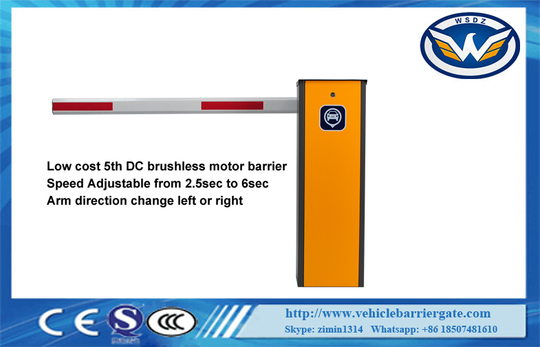
arrier Gate 6m Arm with DC24V Brushless Motor For Parking lot SYSTE